Keywords: DMA, Mechanical properties, Thin sheets, Electrode sheets, Battery material, tension, bending, modulus
RH144
Abstract
Thin sheets are integral to modern manufacturing and engineering due to their high strength-to-weight ratio and versatility. They are used in the automotive, aerospace, construction, electronics, furniture, and packaging industries. The mechanical properties of these sheets, such as stiffness and flexibility, are critical for application performance. Dynamic mechanical analyzers and dynamic mechanical analysis (both referred to as “DMA”) offer detailed insights into the mechanical and viscoelastic properties of thin sheets but obtaining reliable data from these sheets is challenging. Using a coated battery cathode sheet, this note demonstrates best practices for handling thin sheets with the TA Instruments™ Discovery™ DMA 850 in both tension and bending modes.
Introduction
Battery electrodes are just one example of thin sheets used in engineering applications. During manufacturing, thin sheets, including electrode sheets, undergo mechanical stresses such as tension and bending. DMA is crucial for assessing the mechanical integrity of thin sheets, helping ensure they resist deformation and cracking. DMA also effectively monitors the quality of these sheets throughout production by measuring various mechanical properties, including modulus, stress relaxation, and glass transition temperature. By detecting mechanical anomalies early, manufacturers can prevent defective materials from being assembled, reducing waste and improving overall product quality. However, due to the thin nature of these sheets, achieving repeatable and reliable results can be challenging because of clamping and handling difficulties, material inhomogeneity, and instrument limitations. This note offers best practices and guidance for DMA testing of thin sheets [1-5].
Experimental
Material
For this work, a Nickel-Manganese-Cobalt (NMC)-based electrode sheet from NEI Corporation was used. The sheet has a thickness of approximately 0.08 mm and is composed of 90% active material, 5% polyvinylidene fluoride (PVDF) binder, and 5% carbon black. The electrode sheet is cast on aluminum current collectors, serving as cathodes for lithium-ion batteries. The aluminum current collector has a thickness of 0.02 mm. More than three films were cut from this sheet, and one film was cut from the aluminum current collector.
Clamps – DMA 850
Cantilever clamps (Figure 1A) are used for general mechanical testing such as flexural tests. Single and dual cantilevers each have distinct characteristics, advantages, and applications. A single cantilever, fixed at one end and free at the other, offers greater flexibility and versatility, making it suitable for a wide range of materials. In contrast, a dual cantilever, with both ends fixed and a central bending section, provides enhanced stability and higher load capacity.
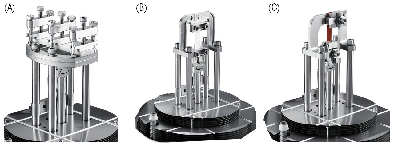
The DMA 850 tension film clamp (two-screw), shown in Figure 1B, is designed for thin films up to 2 mm thick, allowing for the determination of elastic modulus (E’), also referred to as Young’s Modulus or the storage modulus. E’ quantifies a material’s resistance to elastic (reversible) deformation under load. It is a measure of the stiffness of a material in tension [6, 7]. The sample is held in tension, with a small preload to prevent wrinkles or folding, between a fixed upper clamp and a movable lower clamp.
The differences between cantilever and tension clamps in measuring modulus primarily revolve around the type of deformation they apply and the materials they are best suited for. Cantilever clamps measure modulus by applying a bending force to the sample. This setup is ideal for materials that can maintain their shape under bending stress, providing insights into their flexural properties. In contrast, tension clamps measure modulus by applying a tensile force, stretching the sample along its length. This method is particularly suitable for thin films, fibers, and other elongated materials where tensile properties are critical. Tension clamps ensure uniform clamping pressure, reducing the risk of sample slippage and providing accurate tensile property measurements.
The dual surface film tension clamp (single screw), shown in Figure 1C, features a second clamp face with two thin, ridged surfaces at the top and bottom. This ridged clamp face is specifically designed for situations where the thin film under-study slips out of the clamp during testing.
It is crucial to note that the choice of clamps significantly impacts measurement accuracy. Clamps must be properly calibrated before each experiment, with specific calibrations required for different clamps, including mass and position. Ensuring successful calibration prior to the experimental procedure is essential for the reliability of the data. Additionally, the dimensions of the sample must be accurately measured before the experiment and clamped with appropriate tightening [1, 8].
Methods
In this note, for simplicity and ease of comparison, only one test was conducted: a strain amplitude sweep test in both tension and bending modes. This test was utilized to demonstrate how to optimize thin electrode film handling and serves as a first step, measuring the modulus and identifying the linear viscoelastic region.
These strain amplitude sweep tests were conducted using different clamps, as detailed in Table 1. The following section provides a more detailed explanation on how to select appropriate clamps to achieve the desired results.
Table 1. Strain amplitude sweep tests in both tension and bending modes
| Test | Clamps | Measured parameter | Test parameters |
|---|---|---|---|
| Figure 3 | Two-screw tension film clamp | Elastic modulus | Frequency: 0.1 Hz Preload: 0.4 N |
| Figure 4 | Single-screw dual face tension film clamp/Two-screw tension film clamp | Elastic modulus | Frequency: 0.1 Hz Preload: 0.4 N |
| Figure 5 | 10 mm single cantilever/Two-screw tension film clamp | Flexural Modulus/Elastic modulus | Frequency: 0.1 Hz Preload: 0.4 N |
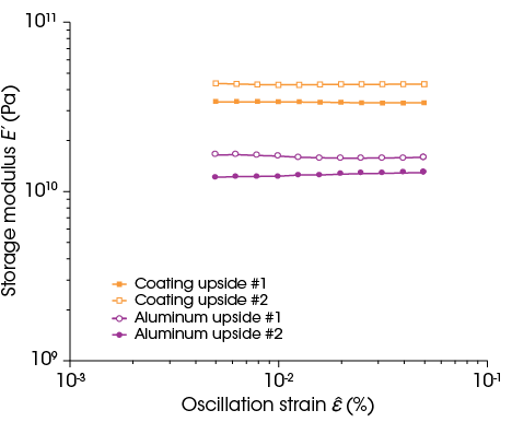
| Figure 6 | 10 mm single cantilever | Flexural Modulus | Frequency: 0.1 Hz |
Results and Discussion
Best practices for testing in tension mode
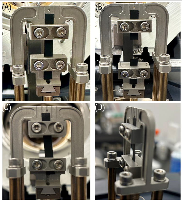
The best practice when mounting sheet samples on a tension clamp is to fix one side of the film to the clamp, pull the opposite side with a tweezer, and then fix it with the proper suggested torque (3 to 5 in-lbs.), ensuring the film is wrinkle-free and not twisted.
To achieve repeatability, it is important to ensure the film is centered, not crooked, and to use the same length of sample between clamps (see Figure 2). Through simple trial and error, a proper range of sample lengths can be identified for good measuring signals, considering the stiffness of the sample. Then, make sure to keep the sample length constant.
For thin films prone to breaking, it is crucial to optimize the combination of applied frequency, preload, and strain range to successfully identify the linear-viscoelastic region and obtain inphase torque and displacement signals. Typical preload forces range from 0.01 to 0.5 N, depending on the sample’s stiffness, and should be just enough to keep the sample taut without causing deformation or creeping.
Several tests were conducted, varying the preload, frequency, and strain range until the optimal values were determined. The preload was set at 0.4 N, and a frequency of 0.1 Hz was chosen for the test. Given the frequency-dependence of some tests, it is advisable to maintain a consistent frequency for all dynamic oscillatory tests throughout the study.
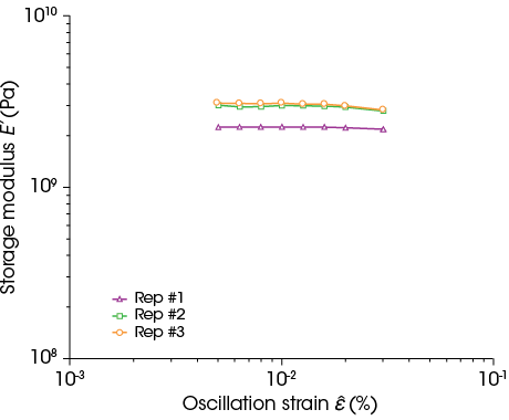
Strain amplitude sweep tests were conducted using a two screw tension film clamp on samples from the electrode sheet to determine E’.
Figure 3 demonstrates that the E’ of the cathode sheet measured ranges between 2−3×10⁹ Pa. This discrepancy may stem from the combined influence of the coating of the sheet or the natural variability of the DMA measurements.
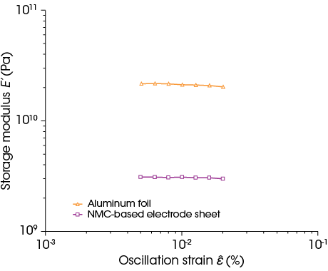
A comparative test was conducted to evaluate E’ of uncoated versus coated aluminum foil. Due to the small thickness of 0.02 mm and the smooth surface of the aluminum foil, a dual-face single screw tension clamp was used to prevent slippage during testing (see Figure 1C). It is important to be aware of both types of tension clamps TA Instruments offers and choose the proper one for the process under-study. Any form of slippage during the test will significantly affect the data.
The results in Figure 4 show that the elastic modulus of the coated aluminum foil was lower than that of the uncoated aluminum foil. This reduction is attributed to the coating, which increases the film’s thickness fourfold with a material possessing lower stiffness than aluminum. Consequently, the overall stiffness or elastic modulus of the coated sheet is diminished. These findings underscore the necessity of considering both dimensional and material properties when assessing the mechanical performance of composite-like structures.
Best practices for testing in bending mode
For bending mode, a 3-point bending clamp is unsuitable for thin sheets. Due to the low stiffness of the sheet, a 10 mm single cantilever was selected to enhance stiffness and achieve more reliable results. Available sizes for single cantilever clamps are 4 mm, 10 mm, and 17.5 mm.
For DMA measurements, the machine stiffness range is fixed at 102 – 107 N/m. If the sample’s stiffness is insufficient, the sample length can be reduced or the thickness increased. The film thickness should not exceed 5 mm, and the width of the rectangular film should be between 5 and 15 mm.
When using the single cantilever clamp, the sample length is defined by the distance between the fixed and movable clamps. Due to the flexibility of the drive shaft, the actual sample length may slightly differ from the default values after tightening. It is crucial to ensure the sample is clamped in an almost perfectly horizontal position. To achieve this, first mount the sample on the movable clamp, then stretch it carefully. Once it is perfectly horizontal, lock the shaft and mount the sample on the fixed clamp.
To achieve the best results with either single or dual cantilever clamps, TA Instruments recommends that the length-to-thickness ratio of the sample be greater than or equal to ten.
Pre-load is not required for the cantilever clamp, and maintaining a constant frequency throughout the study remains important.
In bending, the storage modulus is referred to as the flexural modulus and measures a material’s resistance to bending. It represents the ratio of stress to strain during bending. Considering that tensile force results in uniform stress distribution, while bending force creates a gradient of stress across the sample’s cross-section, flexural modulus can differ from elastic modulus, particularly in composite-like materials [7].The flexural modulus is often higher than the tensile modulus for the same material because the bending test involves both tensile and compressive stresses, making the material appear stiffer [7, 9].
Figure 5 shows that the measured flexural modulus is an order of magnitude higher than the obtained elastic modulus. Additionally, the results indicate slight discrepancy, as previously observed through measurements using a two-screw film tension clamp [4, 10, 3].
Figure 6 illustrates that clamping the sheets in different directions yielded different results. When the sheets were clamped with the coating side up, higher flexural modulus values were obtained compared to clamping with the aluminum side up in the cantilever clamp. This difference stems from the anisotropy of these samples. When testing materials with a composite-like structure in bending, the influence of surface layers—specifically, which layer is outer or inner—is significant [2, 10, 9], thus its influence on measured modulus values should be noted.

Conclusions
This note discusses the best practices for testing thin sheets in tension and bending using DMA. An NMC-based cathode sheet was used to demonstrate the importance of clamp selection and sample setup in the clamps for obtaining mechanical properties, including moduli measurements, of thin sheets.
- The two-screw clamp was employed for the coated sheet, while a dual-face clamp with a ridged surface was used for the thinner and smoother aluminum foil to mitigate any possibility of slippage.
- A 10 mm single cantilever was shown to be appropriate for this thin film measurement, providing reliable and repeatable data. The flexural modulus was also obtained and found to be higher than the elastic modulus.
- Importantly, the direction of clamping during bending affected the measured modulus, showing different mechanical properties based on the direction of testing versus the coating location. This is an important consideration when rolling these sheets for storage or transportation.
References
- P. Sudeshna, P. M. Ajayan and T. N. Narayanan, “Dynamic mechanical analysis in materials science: The Novice’s Tale.,” Oxford Open Materials Science, p. itaa001, 2021.
- K. P. Menard and N. Menard, Dynamic mechanical analysis, CRC press, 2020.
- L. A. Román-Ramírez, G. Apachitei and M. Faraji-Niri, “Effect of coating operating parameters on electrode physical characteristics and final electrochemical performance of lithium-ion batteries,” International Journal of Energy and Environmental Engineering, pp. 943-953, 2022.
- J. Liu, W. Lin, Z. Wang, Y. Wang, T. Chen and J. Zhen, “Elastic Mechanics Study of Layered Li (Ni x Mn y Co z) O 2,” PRX Energy, p. 013012, 2024.
- G. Vegh, A. Madikere Raghunatha Reddy, X. Li, S. Deng, K. Amine and K. Zaghib, “North America’s Potential for an Environmentally Sustainable Nickel, Manganese, and Cobalt Battery Value Chain,” Batteries, p. 377, 2024.
- D. Roylance, “Engineering viscoelasticity,” Massachusetts Institute of Technology, Cambridge, 2001.
- J. W. Callister and D. Rethwisch , Materials science and engineering: an introduction, New York: John wiley & sons, 2020.
- https://www.tainstruments.com, “TRIOS (Version 5.8),” [Software documentation]. TA Instruments-Waters LLC, 2024.
- G. Tolf and C. Per , “Comparison between flexural and tensile modulus of fibre composite,” Fibre Science and Technology, pp. 319-326, 1984.
- A. Etiemble, N. Besnard, A. Bonnin, J. Adrien, T. Douillard, P. Tran-Van, L. Gautier, J. Badot, E. Maire and B. Lestriez, “Multiscale morphological characterization of process induced heterogeneities in blended positive electrodes for lithium–ion batteries,” Journal of Materials Science, pp. 3576-96, 2017.
Acknowledgement
For more information or to request a product quote, please visit www.tainstruments.com to locate your local sales office information.
This paper was written by Behbood Abedi, PhD.
TA Instruments and Discovery are trademarks of Waters Technologies Corporation.
Click here to download the printable version of this application note.

