The most advanced platform for mechanical analysis of solids.
Sales Promotions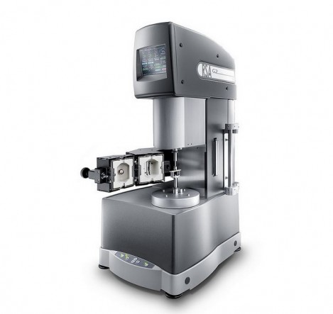
RSA-G2 Specifications
| Minimum Force | 0.0005 N |
| Maximum Force | 35 N |
| Force Resolution | 0.00001 N |
| Dynamic Displacement Range | ±0.00005 to ±1.5 mm |
| Displacement Resolution | 1nm |
| Modulus Range | 103 to 3 x 10¹² Pa |
| Modulus Precision | ± 1% |
| tan δ Sensitivity | 0.0001 |
| tan δ Resolution | 0.00001 |
| Frequency Range | 2 x 10⁻⁵ to 100 Hz |
| Temperature Control | Forced Convection Oven |
| Temperature Range | -150 to 600 °C |
| Heating Rate | 0.1 to 60 °C/min. |
| Cooling Rate | 0.1 to 60 °C/min. |
| Isothermal Stability | 0.1 °C |
The RSA-G2 Provides Independent Measurements of Stress and Strain
The RSA-G2 Provides Independent Measurements of Stress and Strain
When it comes to making the most accurate mechanical measurements, two heads are better than one! The mechanical behavior of solid polymers and other materials is described by material functions such as the modulus or compliance. The modulus is the ratio of stress to strain and the compliance is the ratio of strain to stress. In order to make the purest and most accurate viscoelastic measurements, it is best to measure the fundamental parameters of stress and strain independently. This approach, taken by the TA Instruments RSA-G2, leads to measurements free of instrument artifacts over wide ranges of stress, strain, and frequency
RSA-G2 Design Advantage
RSA-G2 Design Advantage
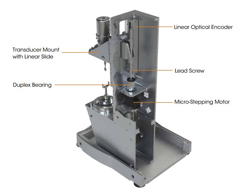
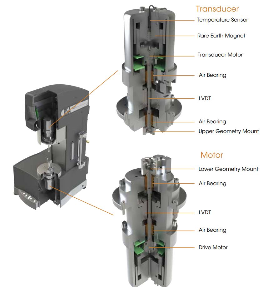
At the heart of the RSA-G2 dual-head solids analyzer is the high performance drive motor and unique transducer. The sample is deformed from the bottom by a direct-drive DC-Servo motor featuring all new electronic DSP control.The force generated in the sample is measured at the top by the patented Force Rebalance Transducer(FRT). The RSA-G2 FRT incorporates a highly sensitive position sensor and linear motor with temperature-compensated rare-earth magnets to ensure the most accurate force measurements. The FRT directly measures sample force from the current required to drive the linear motor in the transducer to maintain zero position. Both the drive motor and transducer incorporate precision air bearings for stiff and frictionless support of linear motion and enhanced force sensitivity. The independent force measurement eliminates motor friction and inertia corrections and translates to the purest force measurement available. The RSA-G2 transducer is mounted to the instrument frame by a linear slide and stepper motor allowing for independent vertical positioning. Transducer motion is via a precision ground lead screw attached to a micro-stepping motor by a rigid preloaded duplex bearing eliminating backlash. A linear optical encoder is mounted directly between the stationary frame and moving bracket for precision head positioning to an accuracy of 0.1 micron. The benefits of the independent transducer positioning are:
- Ease of clamp installation and sample loading
- Compensation of sample expansion/contraction during experiments
- Additional testing capabilities to large deformations such as strain rate tests to pull samples until failure
Temperature Control
Temperature Control
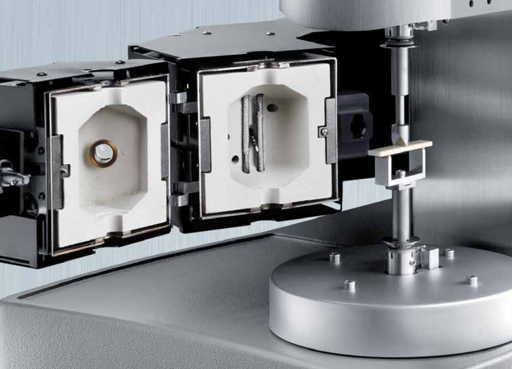
Temperature and environment control for the RSA-G2 is provided by the new Forced Convection Oven, FCO. The FCO is an air/N2 gas convection oven designed for optimum temperature stability, extremely rapid heating and cooling, and ease of use over the temperature range of -150 to 600 °C. The maximum controlled heating rate is 60 °C/min. Obtaining the -150 °C minimum temperature requires an optional liquid nitrogen-cooling device. Alternatively, an optional mechanical cooling is possible down to a minimum temperature of -80 °C. Superior temperature stability is achieved through the use of twin element heaters, which provide counter-rotating airflow in the oven chamber. The FCO can be mounted on either side of the test station, and comes standard with long-life internal LED lamp and window viewing port.
High-Speed Electronics and Data Processing
High-Speed Electronics and Data Processing
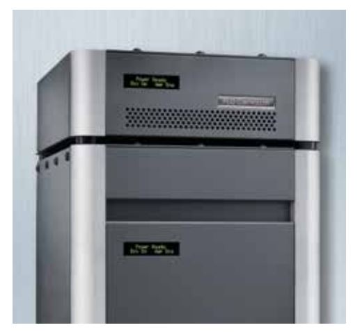
The RSA-G2 is equipped with new high-speed electronics with digital signal processing for transducer measurements and motor control.While many manufacturers cut costs by combining the test station and electronics into a single box, the separate electronics approach of TA Instruments RSA-G2 isolates the precision measurements from heat and vibration. This approach ensures the best sensitivity and data quality from the test station. The electronics enable fully integrated high-speed data acquisition for transient (up to 8000Hz) and oscillation (up to 15000Hz) measurements. The high sampling speed provides superior resolution of magnitude and phase of the measured signals, and allows much better higher harmonic resolution for automatic analysis during oscillation tests or post Fourier transformation analysis. Higher odd harmonics that occur in the stress (force) signal in oscillation tests are a result of non-linear response. The ratio of the fundamental frequency to odd harmonics, such as 3rd, 5th, etc. can be calculated and stored as a signal. In addition, the real-time waveforms during oscillation tests can be displayed and saved with data points. The intensity ratio and quality and shape of the waveform are invaluable data integrity and validation tools.
Touch-Screen and Keypad
Touch-Screen and Keypad
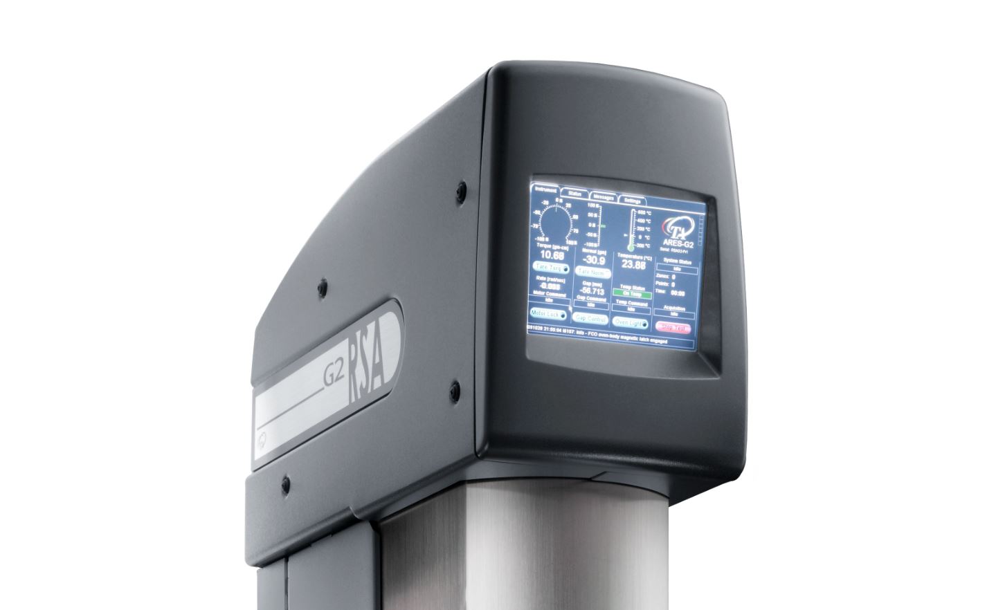
This graphical interface adds a new dimension in ease-of-use. Interactive activities such as clamp zeroing, sample loading, and setting temperature can be performed at the test station. Important instrument status and test information such as temperature, gap, force and motor position are displayed. The touch-screen also provides easy access to instrument settings and diagnostic reporting. The keypad at the base of the instrument allows for easy positioning of the measurement head.
FCO Camera Viewer
FCO Camera Viewer

The FCO can be fitted with an optional camera viewer accessory. The camera includes additional lighting and focus controls which can be adjusted through the TRIOS control software. During the experiment real-time images are displayed in the software and images can be stored with data points for subsequent viewing.
RSA-G2 Clamping Systems
The RSA-G2 features a variety of sample clamps that provide multiple modes of deformation to accommodate a wide range of sample stiffness.The RSA-G2 can easily characterize films,fibers, soft foams,pressure sensitive adhesives (PSA),thermoplastic or thermoset bar samples, high modulus composites, metals, and even medium to high viscosity polymer melts in shear sandwich. All sample clamps are constructed from 17-4 PH steel for maximum rigidity. Standard sample clamps are for use to a maximum temperature of 500 °C. Optional stainless steel sample clamps required for testing to 600 °C are available upon request.
Three-point Bending
 Three-point Bending
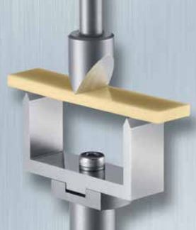
In this mode, the sample is deformed around three-point contacts at both ends and its middle. It is considered a “pure” mode of deformation as the sample is freely supported by fulcrums eliminating clamping effects. It is ideal for testing solid bars of stiff materials, such as composites, ceramics, glassy and semi-crystalline polymers, and metals. The clamp comes standard with every RSA-G2 for routine instrument calibration. Sample Size: includes interchangeable span pieces for sample lengths of 10, 25, and 40 mm. Maximum sample width is 12.8 mm and maximum thickness is 5 mm.
Tension
 Tension
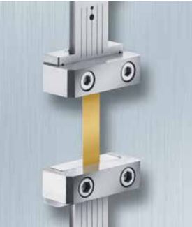
In this mode, the sample is clamped at the top and bottom and placed in tension. The tension clamp is for tensile testing of thin films, such as garbage bags, packaging films, and individual fibers and fiber bundles. Sample Size: Up to 35 mm long, 12.5 mm wide, and 1.5 mm thick.
Dual and Single Cantilever
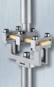 Dual and Single Cantilever
Cantilever modes are also known as “clamped” or “supported” bending modes because the support and deformation points are mechanically fixed to the sample. In dual cantilever the sample is clamped at both ends and at the center. The same clamp is used for single cantilever and the sample is clamped between one end and the central clamp. Single cantilever allows for testing of shorter sample lengths. Cantilever is ideal for general-purpose testing of thermoplastics and elastomers and other highly damped materials, as well as measuring transitions of coatings on substrates.
Sample Size: Up to 38 mm long, 12.5 mm wide, and 1.5 mm thick.
Shear Sandwich
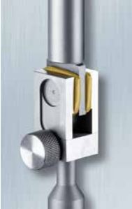 Shear Sandwich
In Shear Sandwich, two equal-size pieces of a material are “sandwiched” between two ends and a central plate. The applied deformation is parallel to the sample thickness and the resultant deformation is simple shear. Typical samples tested include polymer melts, foams, elastomers, gels, pastes, and other soft solids or high viscosity liquids.
Sample Size: Includes three interchangeable central shearing plates to accommodate sample thicknesses of 0.5, 1.0 and 1.5 mm; shearing surface is 15 mm square.
Compression
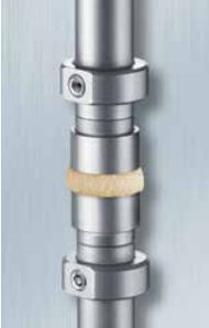 Compression
In this mode, the sample is placed between upper and lower round plates and deformed under various conditions of compression. Compression can be used for testing of many low to moderate modulus materials including foams, elastomers, gels, and other soft solids.
Sample Size: includes three interchangeable sets of plates 8, 15, and 25 mm in diameter; maximum sample thickness is 15 mm.
Contact Lens Fixture
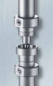 Contact Lens Fixture
The Contact Lens Fixture was designed for testing the dynamic mechanical properties of contact lenses submersed in saline solution over a specific temperature range.
Immersion testing
Immersion testing
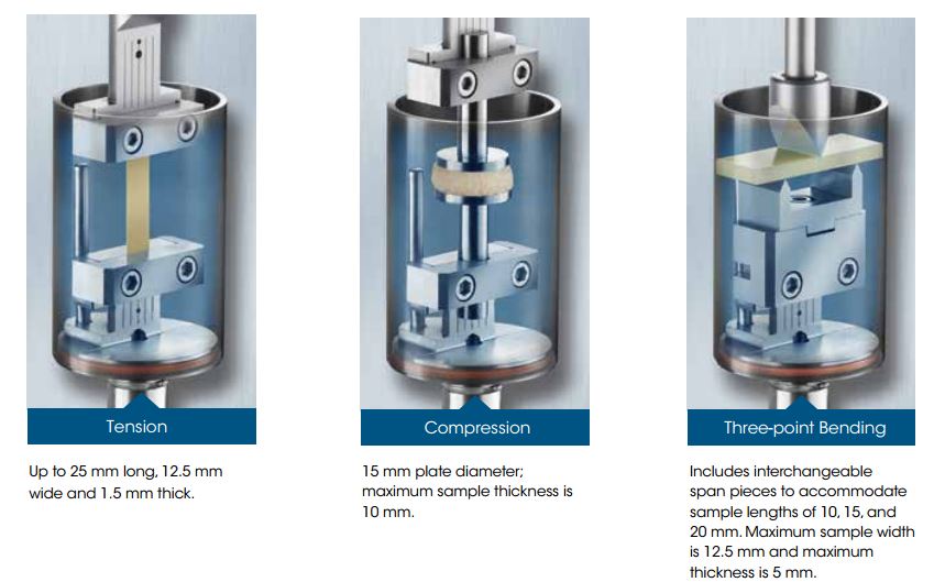
The RSA-G2 Immersion System was designed for mechanical testing of solid materials while immersed in a liquid. The temperature of the fluid environment is measured by a platinum resistance thermometer, PRT, immersed in the liquid. which bypasses the standard control loop of the forced convection oven. Obtainable temperature range is -10 to 200 °C. The system includes tension, compression, and three-point bending geometries. The cup surrounding the sample is removable for easy sample loading.
Immersion Application
Immersion Application
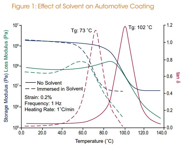
Figure 1 shows the storage modulus, loss modulus, and tan δ for temperature ramp tests run on an automotive coating tested in air and immersed in a solvent. The solvent has a dramatic affect on the mechanical properties of the coating. The water has a plasticizing effect on the material. The glass transition temperature is observed to decrease by almost 29 °C from 102 °C to 73 °C.
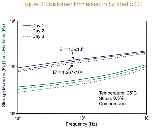
Figure 2 shows a series of frequency sweeps run on an Elastomer sample immersed in synthetic oil at a temperature of 25 °C for three days. The frequency sweep was run on the sample as soon as immersed on day one, and repeated on days two and three. The storage modulus E’, showed a 16% decrease in magnitude over the three days.
Air Chiller System 3
Air Chiller System 3
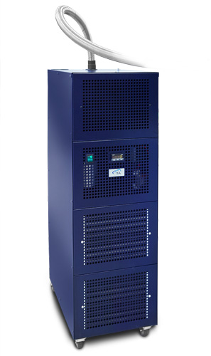 The new Air Chiller System, ACS-3 is a unique gas flow cooling system. It is equipped with a three-stage cascading compressor design, enabling testing to unprecedented temperatures as low as -100°C. This flexible Air Chiller is available for use with the DMA Q800, all DHR Rheometer models with ETC, and the ARES-G2 Rheometer & RSA-G2 Solids Analyzer with FCO. The ACS-3 can help eliminate or reduce liquid nitrogen usage and associated hazards from any laboratory and offers an incredible return on investment estimated between two to three years.
Air Chiller System 2
Air Chiller System 2
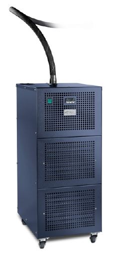 The new ACS-2 is a unique two-stage air chiller system for subambient temperature control and general cooling for rheology and DMA systems, but with a higher minimum temperature than the ACS-3 (-55 °C). Supported instruments and environmental systems include the DMA Q800 with standard furnace, Discovery Hybrid Rheometer models with Environmental Test Chamber and ARES-G2/ RSA-G2 with Forced Convection Oven. The ACS-2 can help eliminate or reduce liquid nitrogen usage and associated hazards from any laboratory and offers an incredible return on investment estimated between two to three years.
Dielectric Analysis
Dielectric Analysis
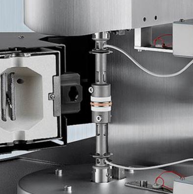
DETA, or Dielectric Thermal Analysis, is a material characterization technique similar to dynamic mechanical analysis except that an oscillating electrical field (AC field) is used in place of a mechanical force (stress) and the oscillating strain is a stored charge (Q) in the sample. Q is measured as its derivative dQ/dt = AC current. DETA measures the degree to which the sample is storing a charge (capacitance) or passing the charge (conductance) through its bulk, which reflects the orientation or mobility of random dipoles. This technique is especially powerful for characterizing polar materials such as PVC, PVDF, PMMA, and PVA, and for monitoring curing kinetics of materials such as epoxy and urethane systems. The wide range of frequencies available in DETA (up to 30 MHz) also extends the measurement range far beyond traditional dynamic mechanical analysis.
The combination of DETA with a high precision RSA-G2 solids analyzer allows for the simultaneous collection of rheological and dielectric information. A special set of parallel plates is connected directly to a dielectric bridge (LCR meter) which imposes a signal at a certain voltage and frequency/ies. The RSA-G2 also enhances stand-alone dielectric measurements by improving sample conditions. DETA measurements are conducted on a material sandwiched between parallel plates, with force applied to ensure good surface contact, and surrounded by an oven for temperature control. In competitive instruments, the permittivity, or dielectric constant, is measured by the ratio of capacitance with the sample in the plates to the capacitance with the same air gap. As temperature changes and expansion of the plates occurs, the gap changes and the accuracy of the permittivity suffers. The RSA-G2 FCO (forced convection oven) temperature control, axial force control with gap temperature compensation capability, and software for interface, results in more accurate DETA measurements.
| RSA-G2 Dielectric Specifications | |
| Geometry | 25 mm PP |
| Temperature System Compatibility | FCO, Force Convection Oven |
| ARES/RSA to DE Bridge Interface | IEEE Internal to Instrument |
| Temperature Range | -150 °C to 350 °C |
| Available Dielectric Bridges |
Keysight E4980A; 20Hz to 2MHz; 0.005 to 20 V Keysight 4285A; 75kHz to 30MHz; 0.005 to 10 V Keysight E4980AL/120; 20 Hz to 1 MHz; 0.001 to 2 V |
Immersion Testing
Immersion Testing
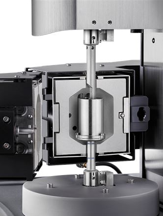
The RSA-G2 Immersion System was designed for mechanical testing of solid materials while immersed in a liquid. The temperature of the fluid environment is measured by a platinum resistance thermometer, PRT, immersed in the liquid. which bypasses the standard control loop of the forced convection oven. Obtainable temperature range is -10 to 200 °C. The system includes tension, compression, and three-point bending geometries. The cup surrounding the sample is removable for easy sample loading.
Dynamic Mechanical Analysis, DMA
Dynamic Mechanical Analysis, DMA
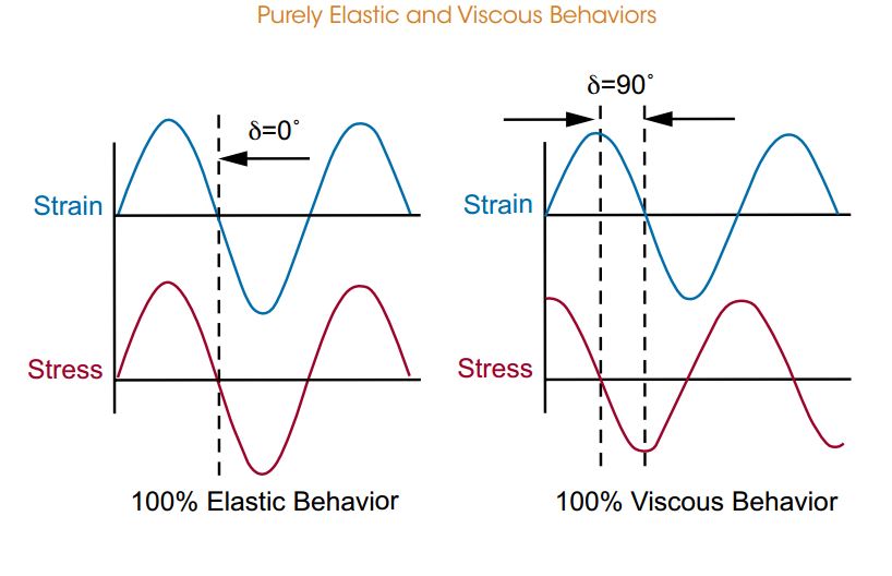
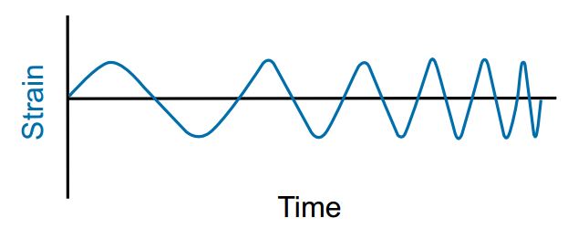
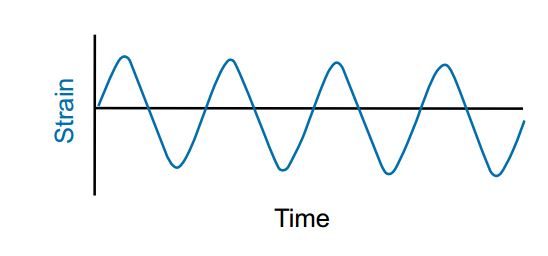
DMA is the most common test type for measuring viscoelastic properties of materials. Both elastic and viscous characteristics of the material can be studied by imposing a sinusoidal strain (or stress) and measuring the resultant sinusoidal stress (or strain) along with the phase difference between the two sinusoidal waves (input and output). The phase angle is zero degrees for purely elastic materials and 90° for purely viscous materials. Viscoelastic materials exhibit a phase angle anywhere between these two ideal cases depending on the rate of deformation. The figures below show these sinusoidal responses along with the variety of rheological parameters obtained. The viscoelastic parameters can be measured as a function of deformation amplitude, frequency, time, and temperature and examples of each important experiment are provided.
Strain Sweep
Strain Sweep
In this test, the frequency and temperature are held constant and the strain is varied. Strain Sweep tests are used to identify the linear viscoelastic region, LVR. Testing within the LVR provides powerful structure-property relationships as a material’s molecular arrangements are never far from equilibrium and the response is a reflection of internal dynamic processes. Figure 3 shows a strain sweep on a filled elastomer sample tested at 10 Hz in dual cantilever bending geometry. At low strains, within the LVR, the modulus is independent of the strain amplitude. At about 0.1% strain the modulus begins to decrease in magnitude showing the end of the LVR. Outside the LVR the output stress response to the input strain is no longer sinusoidal. Non-linear effects show up as higher odd harmonics which the RSA-G2 is able to collect. The figure shows the intensity ratio of the third to first harmonics at each strain value. Strain sweep tests can be used for a variety of additional reasons such as understanding the Mullins Effect in a rubber or comparing the resiliency of materials.
Temperature Ramps
Temperature Ramps
These are the most common DMA experiments. Measuring the viscoelastic properties over a range of temperatures is an extremely sensitive technique for obtaining the α or glass transition temperature, Tg, as well as any additional β or γ transitions in a material. In a temperature ramp, a linear heating rate is applied.Typical heating rates are on the order of 1 to 5 °C/min.The material response is monitored at one or multiple frequencies at an amplitude within the LVR with data taken at defined time interval.
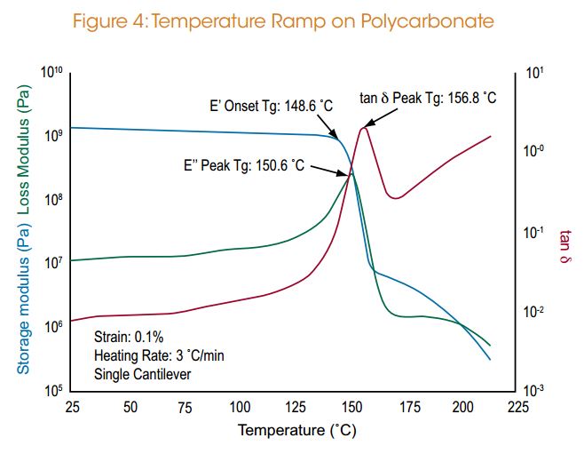
Figure 4 shows a temperature ramp on Polycarbonate run in single cantilever. Note the data start in the glassy region and are measured into the melt demonstrating the advantage of the RSA-G2 technology. Multiple parameters can be used to determine transitions including E’ onset point or peaks in the E” or tan δ. The temperature at which the transition occurs depends on the parameter selected.
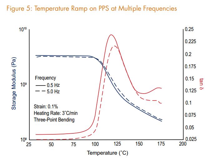
Because the Tg has a kinetic component, it is strongly influenced by the frequency (rate) of deformation. As the frequency increases, the molecular relaxations can only occur at higher temperatures and, as a consequence, the Tg will shift to a higher temperature. An example of the frequency dependence of a glass transition is shown in Figure 5 for a sample of Polyphenyl Sulfide. Note the shape and intensity of the tan δ peak and the slope of the storage modulus in the transition region will be affected.
Frequency Sweep
Frequency Sweep
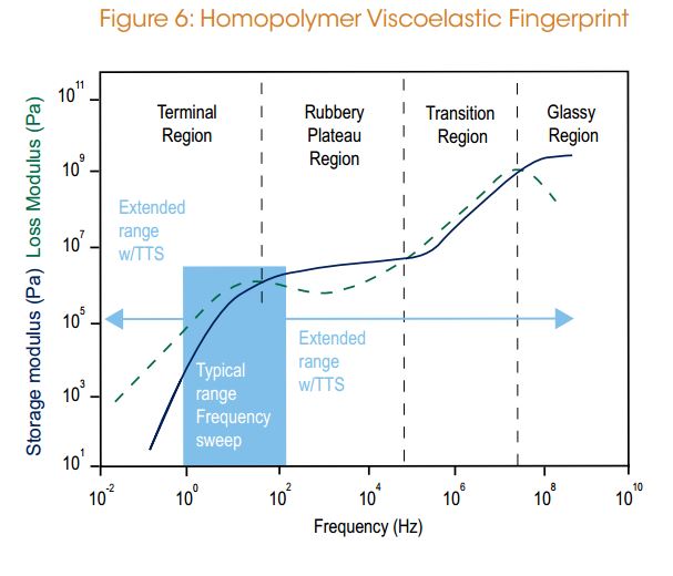
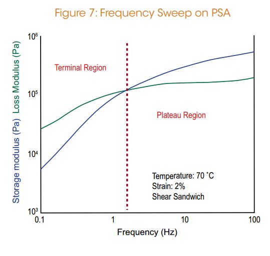
In this test, the temperature and strain are held constant and the frequency is varied. Figure 6 illustrates a viscoelastic fingerprint for a linear homopolymer and shows the variation of E’ and E” as a function of frequency. As frequency is the inverse of time, the curve shows the time-dependent mechanical response, with short times corresponding to solid-like behavior and long times to liquid–like behavior. The magnitude and shape of the E’ (G’) and E”(G”) curves depend on the molecular structure. Frequency sweeps are typically run over a limited range of 0.1 to 100 Hz as shown in Figure 7 for a pressure sensitive adhesive at 70 °C using the RSA-G2 shear sandwich clamp. At this temperature and frequency range, the sample is in the terminal and plateau regions.
Temperature Sweeps
Temperature Sweeps
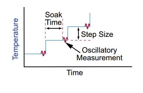
In this test, a step and hold temperature profile is applied. At each temperature step, the sample is held at temperature for a defined amount of time to ensure temperature uniformity in the material. The material response is then measured at one or multiple frequencies at a strain within the LVR.
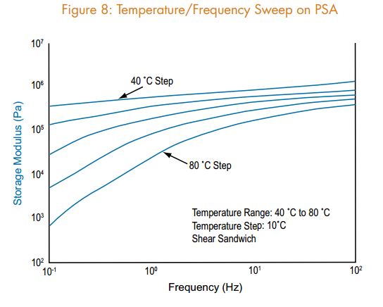
Figure 8 shows results of a temperature sweep on a pressure sensitive adhesive over a temperature range of 40 °C to 80 °C. At each 10 °C step in the sweep, the sample was scanned over a frequency range of 0.1 to 100 Hz. The storage modulus is plotted as a function of frequency for each 10 °C step. This is the method of choice for TimeTemperature Superposition studies as all the frequency dependent data are collected at the same temperature.
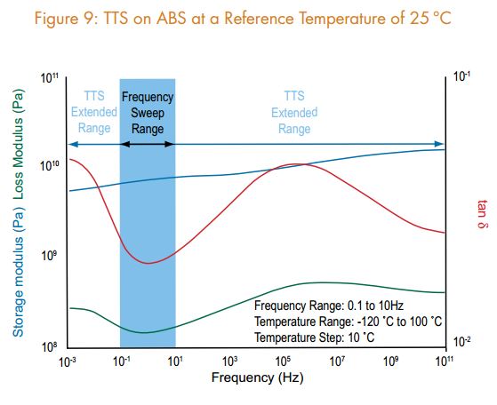
Time-temperature superposition (TTS) is used to extend the frequency range by running a series of frequency sweeps over a wide range of temperature. Figure 9 shows a master curve constructed at a reference temperature of 25 °C for a sample of Acrylonitrilebutydiene-styrene (ABS). In this example the original frequency range of two decades was extended to 14 decades.
Time Sweep
Time Sweep
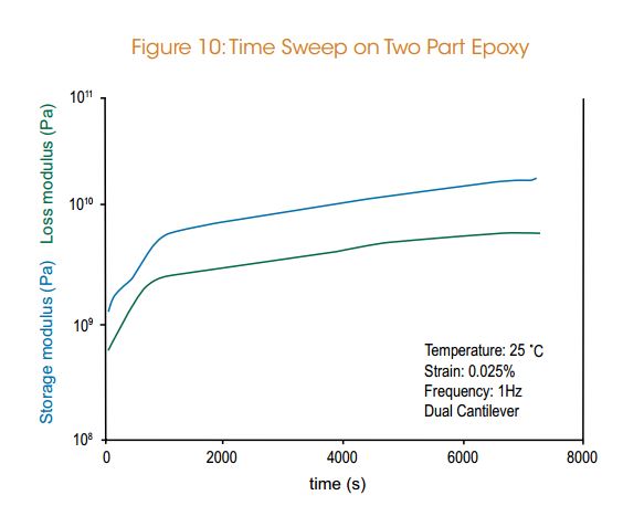
In this test, the temperature, strain, and frequency are all held constant while the viscoelastic properties are measured as a function of time. Time sweep provides important information on time-dependent structural changes such as a curing reaction or fatigue studies. Figure 10 shows an example of a two-part epoxy cured on a supporting fiberglass braid using a dual cantilever clamp. At short times the storage modulus is low and increases in magnitude as the epoxy cures and hardens.
Step Tests: Creep and Stress Relaxation
Step Tests: Creep and Stress Relaxation
Step Tests, including Stress Relaxation and Creep Recovery, are so named because the sample deformation or stress is applied in a step fashion. Both are highly sensitive tests for measuring viscoelastic properties of materials. In creep and recovery, a constant stress is applied to the sample at t1 and the resulting strain is measured over time. At t2 the stress is removed and the recovery (recoil) strain is measured. The creep compliance, D(t), is calculated from the stress and time-dependent strain. In stress relaxation, an instantaneous strain is applied to the sample and held constant. The resulting stress decay is measured as a function of time yielding relaxation modulus E(t) or G(t).

Figure 11 shows an example of creep and recovery for a soft foam material in compression.A stress of 2,000 Pa was applied for 60 sec and strain recovery was monitored for 60 sec.
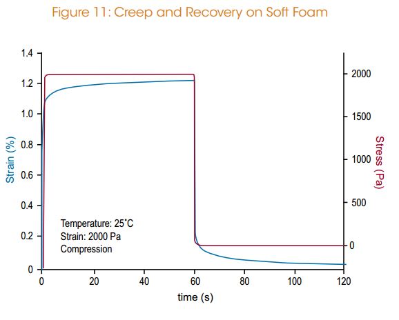
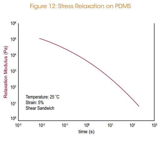
Figure 12 shows the stress relaxation modulus for PDMS in a shear sandwich clamp at 25 ˚C and 5% strain. G(t) is calculated from the time-dependent stress decay divided by the applied strain and provides a quick and easy way to directly measure relaxation times in materials.
Iso-strain and Iso-stress Tests
Iso-strain and Iso-stress Tests
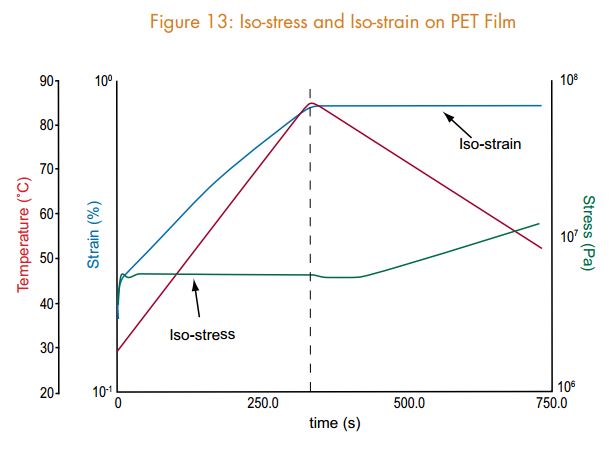
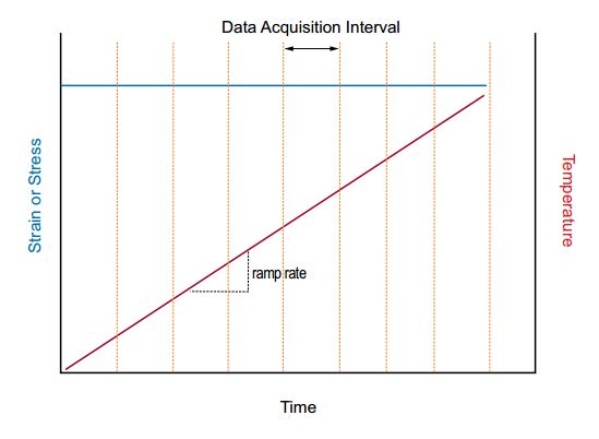
In this mode, the strain or stress is held at a constant value and a linear heating rate is applied. These tests are valuable for assessing mechanical behavior under conditions of fixed load (stress) or fixed deformation (strain). Figure 13 shows a sample of PET film tested in tension geometry under iso-stress conditions with a linear heating rate followed immediately by an iso-strain condition and linear cooling rate. It can be observed in the figure that under iso-stress the strain gets larger as the sample is heated and softens. At a temperature of 85 °C the strain is then held constant and as the sample is cooled, the sample stress gets larger. These test modes are ideal for characterization of shape memory materials.
Axial Tests
Axial Tests
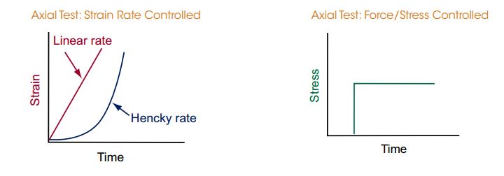
The linear slide and stepper motor for independent vertical positioning of the instrument’s transducer enable the RSA-G2 to conduct additional axial tests for the ultimate testing flexibility. A sample can be deformed under a constant linear strain rate, Hencky strain rate, force, or stress for generating more traditional stress-strain curves.
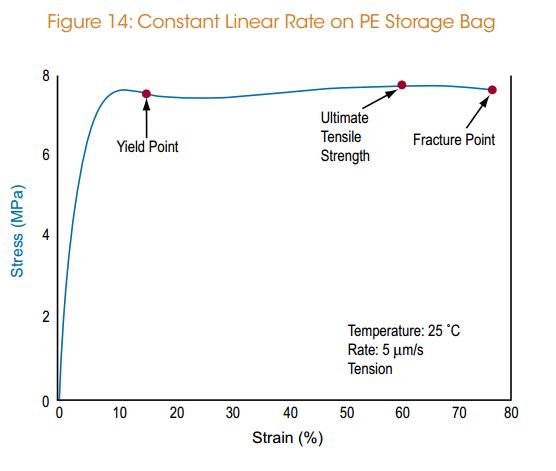
Figure 14 shows a Polyethylene film tested using the tension geometry at 25 °C and a constant linear rate of 5 microns per second. A classical stress-strain curve is observed with yield point, ultimate tensile strength, and fracture point.
Dielectric Temperature Ramp
Dielectric Temperature Ramp
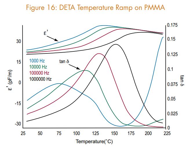
Figure 16 shows an example of a ramp on a PMMA Sample at four different Dielectric Frequencies ranging from 1kHz to 1MHz. It can be seen here that the magnitude of e’ decreases with increasing frequency through the transition region and the peak of the transition in tan d moves to higher temperatures with increasing frequency.
Dielectric Frequency Sweep
Dielectric Frequency Sweep
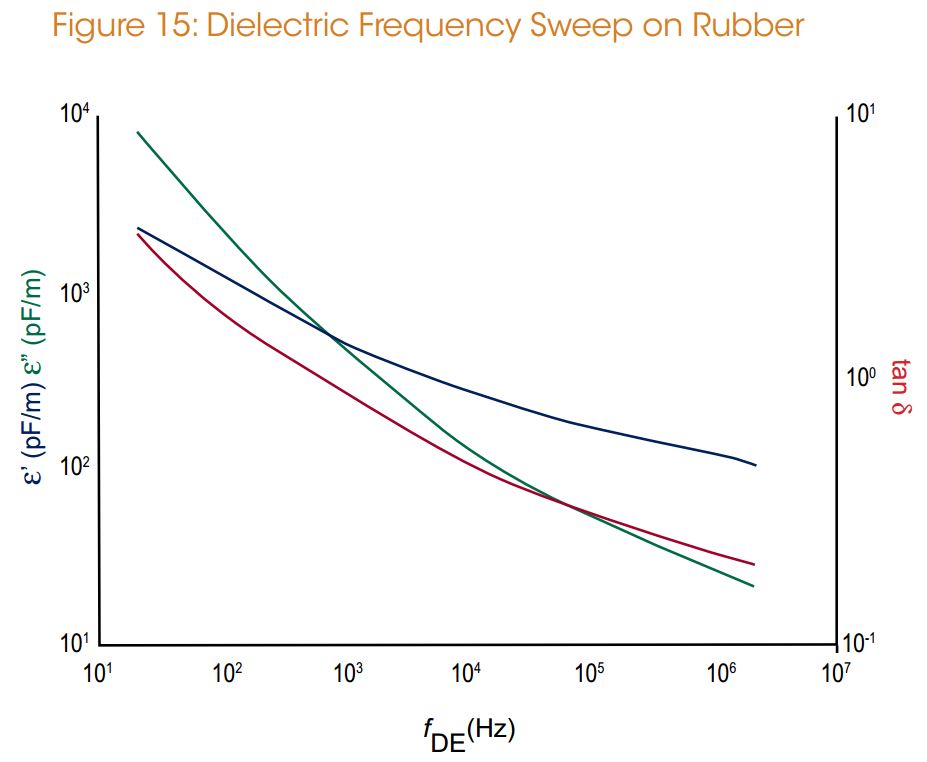
Figure 15 shows an example of a dielectric frequency sweep run on a rubber sample under ambient conditions. Shown are the storage and loss permittivity and loss tangent over a frequency range of 20 Hz to 2 MHz.
- Desc.
-
The new RSA-G2 is the most advanced platform for mechanical analysis of solids. The separate motor and transducer technology of the RSA-G2 insures the purest mechanical data through independent control of deformation and measurement of stress. It is capable of performing the most accurate DMA measurements as well as many additional experiments including creep and recovery, stress relaxation, stress ramps, strain rate ramps, iso-strain, iso-force, fatigue, multi-wave, arbitrary waveform, and dielectric thermal analysis. With such a broad range of solid analysis techniques, the RSA-G2 is uniquely positioned to address the widest range of applications from the R&D bench to the quality control lab. This new high-performance instrument represents the fourth generation of dual head mechanical analyzers, featuring a new force convection oven for precise and accurate temperature control, extensive array of geometries to accommodate the widest range of sample shapes and stiffness, and immersion testing capability. In addition, the RSA-G2 doubles as a DETA, or Dielectric Thermal Analyzer, for stand-alone or simultaneous measurements.
- Specs.
-
RSA-G2 Specifications
Minimum Force 0.0005 N Maximum Force 35 N Force Resolution 0.00001 N Dynamic Displacement Range ±0.00005 to ±1.5 mm Displacement Resolution 1nm Modulus Range 103 to 3 x 10¹² Pa Modulus Precision ± 1% tan δ Sensitivity 0.0001 tan δ Resolution 0.00001 Frequency Range 2 x 10⁻⁵ to 100 Hz Temperature Control Forced Convection Oven Temperature Range -150 to 600 °C Heating Rate 0.1 to 60 °C/min. Cooling Rate 0.1 to 60 °C/min. Isothermal Stability 0.1 °C - Features
-
The RSA-G2 Provides Independent Measurements of Stress and Strain
The RSA-G2 Provides Independent Measurements of Stress and Strain

When it comes to making the most accurate mechanical measurements, two heads are better than one! The mechanical behavior of solid polymers and other materials is described by material functions such as the modulus or compliance. The modulus is the ratio of stress to strain and the compliance is the ratio of strain to stress. In order to make the purest and most accurate viscoelastic measurements, it is best to measure the fundamental parameters of stress and strain independently. This approach, taken by the TA Instruments RSA-G2, leads to measurements free of instrument artifacts over wide ranges of stress, strain, and frequency
RSA-G2 Design Advantage
RSA-G2 Design Advantage

At the heart of the RSA-G2 dual-head solids analyzer is the high performance drive motor and unique transducer. The sample is deformed from the bottom by a direct-drive DC-Servo motor featuring all new electronic DSP control.The force generated in the sample is measured at the top by the patented Force Rebalance Transducer(FRT). The RSA-G2 FRT incorporates a highly sensitive position sensor and linear motor with temperature-compensated rare-earth magnets to ensure the most accurate force measurements. The FRT directly measures sample force from the current required to drive the linear motor in the transducer to maintain zero position. Both the drive motor and transducer incorporate precision air bearings for stiff and frictionless support of linear motion and enhanced force sensitivity. The independent force measurement eliminates motor friction and inertia corrections and translates to the purest force measurement available. The RSA-G2 transducer is mounted to the instrument frame by a linear slide and stepper motor allowing for independent vertical positioning. Transducer motion is via a precision ground lead screw attached to a micro-stepping motor by a rigid preloaded duplex bearing eliminating backlash. A linear optical encoder is mounted directly between the stationary frame and moving bracket for precision head positioning to an accuracy of 0.1 micron. The benefits of the independent transducer positioning are:
- Ease of clamp installation and sample loading
- Compensation of sample expansion/contraction during experiments
- Additional testing capabilities to large deformations such as strain rate tests to pull samples until failure
Temperature Control
Temperature Control

Temperature and environment control for the RSA-G2 is provided by the new Forced Convection Oven, FCO. The FCO is an air/N2 gas convection oven designed for optimum temperature stability, extremely rapid heating and cooling, and ease of use over the temperature range of -150 to 600 °C. The maximum controlled heating rate is 60 °C/min. Obtaining the -150 °C minimum temperature requires an optional liquid nitrogen-cooling device. Alternatively, an optional mechanical cooling is possible down to a minimum temperature of -80 °C. Superior temperature stability is achieved through the use of twin element heaters, which provide counter-rotating airflow in the oven chamber. The FCO can be mounted on either side of the test station, and comes standard with long-life internal LED lamp and window viewing port.
High-Speed Electronics and Data Processing
High-Speed Electronics and Data Processing

The RSA-G2 is equipped with new high-speed electronics with digital signal processing for transducer measurements and motor control.While many manufacturers cut costs by combining the test station and electronics into a single box, the separate electronics approach of TA Instruments RSA-G2 isolates the precision measurements from heat and vibration. This approach ensures the best sensitivity and data quality from the test station. The electronics enable fully integrated high-speed data acquisition for transient (up to 8000Hz) and oscillation (up to 15000Hz) measurements. The high sampling speed provides superior resolution of magnitude and phase of the measured signals, and allows much better higher harmonic resolution for automatic analysis during oscillation tests or post Fourier transformation analysis. Higher odd harmonics that occur in the stress (force) signal in oscillation tests are a result of non-linear response. The ratio of the fundamental frequency to odd harmonics, such as 3rd, 5th, etc. can be calculated and stored as a signal. In addition, the real-time waveforms during oscillation tests can be displayed and saved with data points. The intensity ratio and quality and shape of the waveform are invaluable data integrity and validation tools.
Touch-Screen and Keypad
Touch-Screen and Keypad

This graphical interface adds a new dimension in ease-of-use. Interactive activities such as clamp zeroing, sample loading, and setting temperature can be performed at the test station. Important instrument status and test information such as temperature, gap, force and motor position are displayed. The touch-screen also provides easy access to instrument settings and diagnostic reporting. The keypad at the base of the instrument allows for easy positioning of the measurement head.
FCO Camera Viewer
FCO Camera Viewer

The FCO can be fitted with an optional camera viewer accessory. The camera includes additional lighting and focus controls which can be adjusted through the TRIOS control software. During the experiment real-time images are displayed in the software and images can be stored with data points for subsequent viewing.
- Clamping System
-
RSA-G2 Clamping Systems
The RSA-G2 features a variety of sample clamps that provide multiple modes of deformation to accommodate a wide range of sample stiffness.The RSA-G2 can easily characterize films,fibers, soft foams,pressure sensitive adhesives (PSA),thermoplastic or thermoset bar samples, high modulus composites, metals, and even medium to high viscosity polymer melts in shear sandwich. All sample clamps are constructed from 17-4 PH steel for maximum rigidity. Standard sample clamps are for use to a maximum temperature of 500 °C. Optional stainless steel sample clamps required for testing to 600 °C are available upon request.
Three-point Bending
 Three-point Bending
In this mode, the sample is deformed around three-point contacts at both ends and its middle. It is considered a “pure” mode of deformation as the sample is freely supported by fulcrums eliminating clamping effects. It is ideal for testing solid bars of stiff materials, such as composites, ceramics, glassy and semi-crystalline polymers, and metals. The clamp comes standard with every RSA-G2 for routine instrument calibration. Sample Size: includes interchangeable span pieces for sample lengths of 10, 25, and 40 mm. Maximum sample width is 12.8 mm and maximum thickness is 5 mm.
Tension
 Tension
In this mode, the sample is clamped at the top and bottom and placed in tension. The tension clamp is for tensile testing of thin films, such as garbage bags, packaging films, and individual fibers and fiber bundles. Sample Size: Up to 35 mm long, 12.5 mm wide, and 1.5 mm thick.
Dual and Single Cantilever
 Dual and Single Cantilever
Cantilever modes are also known as “clamped” or “supported” bending modes because the support and deformation points are mechanically fixed to the sample. In dual cantilever the sample is clamped at both ends and at the center. The same clamp is used for single cantilever and the sample is clamped between one end and the central clamp. Single cantilever allows for testing of shorter sample lengths. Cantilever is ideal for general-purpose testing of thermoplastics and elastomers and other highly damped materials, as well as measuring transitions of coatings on substrates.
Sample Size: Up to 38 mm long, 12.5 mm wide, and 1.5 mm thick.
Shear Sandwich
 Shear Sandwich
In Shear Sandwich, two equal-size pieces of a material are “sandwiched” between two ends and a central plate. The applied deformation is parallel to the sample thickness and the resultant deformation is simple shear. Typical samples tested include polymer melts, foams, elastomers, gels, pastes, and other soft solids or high viscosity liquids.
Sample Size: Includes three interchangeable central shearing plates to accommodate sample thicknesses of 0.5, 1.0 and 1.5 mm; shearing surface is 15 mm square.
Compression
 Compression
In this mode, the sample is placed between upper and lower round plates and deformed under various conditions of compression. Compression can be used for testing of many low to moderate modulus materials including foams, elastomers, gels, and other soft solids.
Sample Size: includes three interchangeable sets of plates 8, 15, and 25 mm in diameter; maximum sample thickness is 15 mm.
Contact Lens Fixture
 Contact Lens Fixture
The Contact Lens Fixture was designed for testing the dynamic mechanical properties of contact lenses submersed in saline solution over a specific temperature range.
Immersion testing
Immersion testing

The RSA-G2 Immersion System was designed for mechanical testing of solid materials while immersed in a liquid. The temperature of the fluid environment is measured by a platinum resistance thermometer, PRT, immersed in the liquid. which bypasses the standard control loop of the forced convection oven. Obtainable temperature range is -10 to 200 °C. The system includes tension, compression, and three-point bending geometries. The cup surrounding the sample is removable for easy sample loading.
Immersion Application
Immersion Application

Figure 1 shows the storage modulus, loss modulus, and tan δ for temperature ramp tests run on an automotive coating tested in air and immersed in a solvent. The solvent has a dramatic affect on the mechanical properties of the coating. The water has a plasticizing effect on the material. The glass transition temperature is observed to decrease by almost 29 °C from 102 °C to 73 °C.

Figure 2 shows a series of frequency sweeps run on an Elastomer sample immersed in synthetic oil at a temperature of 25 °C for three days. The frequency sweep was run on the sample as soon as immersed on day one, and repeated on days two and three. The storage modulus E’, showed a 16% decrease in magnitude over the three days.
- Accessories
-
Air Chiller System 3
Air Chiller System 3
 The new Air Chiller System, ACS-3 is a unique gas flow cooling system. It is equipped with a three-stage cascading compressor design, enabling testing to unprecedented temperatures as low as -100°C. This flexible Air Chiller is available for use with the DMA Q800, all DHR Rheometer models with ETC, and the ARES-G2 Rheometer & RSA-G2 Solids Analyzer with FCO. The ACS-3 can help eliminate or reduce liquid nitrogen usage and associated hazards from any laboratory and offers an incredible return on investment estimated between two to three years.
Air Chiller System 2
Air Chiller System 2
 The new ACS-2 is a unique two-stage air chiller system for subambient temperature control and general cooling for rheology and DMA systems, but with a higher minimum temperature than the ACS-3 (-55 °C). Supported instruments and environmental systems include the DMA Q800 with standard furnace, Discovery Hybrid Rheometer models with Environmental Test Chamber and ARES-G2/ RSA-G2 with Forced Convection Oven. The ACS-2 can help eliminate or reduce liquid nitrogen usage and associated hazards from any laboratory and offers an incredible return on investment estimated between two to three years.
Dielectric Analysis
Dielectric Analysis

DETA, or Dielectric Thermal Analysis, is a material characterization technique similar to dynamic mechanical analysis except that an oscillating electrical field (AC field) is used in place of a mechanical force (stress) and the oscillating strain is a stored charge (Q) in the sample. Q is measured as its derivative dQ/dt = AC current. DETA measures the degree to which the sample is storing a charge (capacitance) or passing the charge (conductance) through its bulk, which reflects the orientation or mobility of random dipoles. This technique is especially powerful for characterizing polar materials such as PVC, PVDF, PMMA, and PVA, and for monitoring curing kinetics of materials such as epoxy and urethane systems. The wide range of frequencies available in DETA (up to 30 MHz) also extends the measurement range far beyond traditional dynamic mechanical analysis.
The combination of DETA with a high precision RSA-G2 solids analyzer allows for the simultaneous collection of rheological and dielectric information. A special set of parallel plates is connected directly to a dielectric bridge (LCR meter) which imposes a signal at a certain voltage and frequency/ies. The RSA-G2 also enhances stand-alone dielectric measurements by improving sample conditions. DETA measurements are conducted on a material sandwiched between parallel plates, with force applied to ensure good surface contact, and surrounded by an oven for temperature control. In competitive instruments, the permittivity, or dielectric constant, is measured by the ratio of capacitance with the sample in the plates to the capacitance with the same air gap. As temperature changes and expansion of the plates occurs, the gap changes and the accuracy of the permittivity suffers. The RSA-G2 FCO (forced convection oven) temperature control, axial force control with gap temperature compensation capability, and software for interface, results in more accurate DETA measurements.
RSA-G2 Dielectric Specifications Geometry 25 mm PP Temperature System Compatibility FCO, Force Convection Oven ARES/RSA to DE Bridge Interface IEEE Internal to Instrument Temperature Range -150 °C to 350 °C Available Dielectric Bridges Keysight E4980A; 20Hz to 2MHz; 0.005 to 20 V
Keysight 4285A; 75kHz to 30MHz; 0.005 to 10 V
Keysight E4980AL/120; 20 Hz to 1 MHz; 0.001 to 2 V
Immersion Testing
Immersion Testing

The RSA-G2 Immersion System was designed for mechanical testing of solid materials while immersed in a liquid. The temperature of the fluid environment is measured by a platinum resistance thermometer, PRT, immersed in the liquid. which bypasses the standard control loop of the forced convection oven. Obtainable temperature range is -10 to 200 °C. The system includes tension, compression, and three-point bending geometries. The cup surrounding the sample is removable for easy sample loading.
- Capabilities
-
Dynamic Mechanical Analysis, DMA
Dynamic Mechanical Analysis, DMA

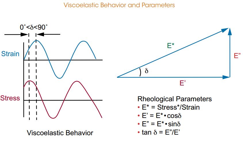
DMA is the most common test type for measuring viscoelastic properties of materials. Both elastic and viscous characteristics of the material can be studied by imposing a sinusoidal strain (or stress) and measuring the resultant sinusoidal stress (or strain) along with the phase difference between the two sinusoidal waves (input and output). The phase angle is zero degrees for purely elastic materials and 90° for purely viscous materials. Viscoelastic materials exhibit a phase angle anywhere between these two ideal cases depending on the rate of deformation. The figures below show these sinusoidal responses along with the variety of rheological parameters obtained. The viscoelastic parameters can be measured as a function of deformation amplitude, frequency, time, and temperature and examples of each important experiment are provided.

Strain Sweep
Strain Sweep

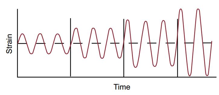
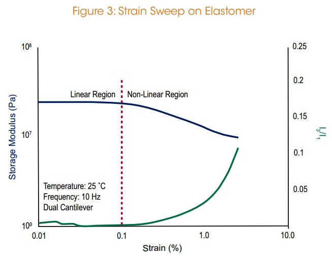
In this test, the frequency and temperature are held constant and the strain is varied. Strain Sweep tests are used to identify the linear viscoelastic region, LVR. Testing within the LVR provides powerful structure-property relationships as a material’s molecular arrangements are never far from equilibrium and the response is a reflection of internal dynamic processes. Figure 3 shows a strain sweep on a filled elastomer sample tested at 10 Hz in dual cantilever bending geometry. At low strains, within the LVR, the modulus is independent of the strain amplitude. At about 0.1% strain the modulus begins to decrease in magnitude showing the end of the LVR. Outside the LVR the output stress response to the input strain is no longer sinusoidal. Non-linear effects show up as higher odd harmonics which the RSA-G2 is able to collect. The figure shows the intensity ratio of the third to first harmonics at each strain value. Strain sweep tests can be used for a variety of additional reasons such as understanding the Mullins Effect in a rubber or comparing the resiliency of materials.

Temperature Ramps
Temperature Ramps

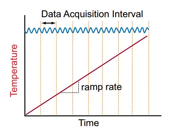
These are the most common DMA experiments. Measuring the viscoelastic properties over a range of temperatures is an extremely sensitive technique for obtaining the α or glass transition temperature, Tg, as well as any additional β or γ transitions in a material. In a temperature ramp, a linear heating rate is applied.Typical heating rates are on the order of 1 to 5 °C/min.The material response is monitored at one or multiple frequencies at an amplitude within the LVR with data taken at defined time interval.

Figure 4 shows a temperature ramp on Polycarbonate run in single cantilever. Note the data start in the glassy region and are measured into the melt demonstrating the advantage of the RSA-G2 technology. Multiple parameters can be used to determine transitions including E’ onset point or peaks in the E” or tan δ. The temperature at which the transition occurs depends on the parameter selected.

Because the Tg has a kinetic component, it is strongly influenced by the frequency (rate) of deformation. As the frequency increases, the molecular relaxations can only occur at higher temperatures and, as a consequence, the Tg will shift to a higher temperature. An example of the frequency dependence of a glass transition is shown in Figure 5 for a sample of Polyphenyl Sulfide. Note the shape and intensity of the tan δ peak and the slope of the storage modulus in the transition region will be affected.
Frequency Sweep
Frequency Sweep

In this test, the temperature and strain are held constant and the frequency is varied. Figure 6 illustrates a viscoelastic fingerprint for a linear homopolymer and shows the variation of E’ and E” as a function of frequency. As frequency is the inverse of time, the curve shows the time-dependent mechanical response, with short times corresponding to solid-like behavior and long times to liquid–like behavior. The magnitude and shape of the E’ (G’) and E”(G”) curves depend on the molecular structure. Frequency sweeps are typically run over a limited range of 0.1 to 100 Hz as shown in Figure 7 for a pressure sensitive adhesive at 70 °C using the RSA-G2 shear sandwich clamp. At this temperature and frequency range, the sample is in the terminal and plateau regions.


Temperature Sweeps
Temperature Sweeps

In this test, a step and hold temperature profile is applied. At each temperature step, the sample is held at temperature for a defined amount of time to ensure temperature uniformity in the material. The material response is then measured at one or multiple frequencies at a strain within the LVR.
Figure 8 shows results of a temperature sweep on a pressure sensitive adhesive over a temperature range of 40 °C to 80 °C. At each 10 °C step in the sweep, the sample was scanned over a frequency range of 0.1 to 100 Hz. The storage modulus is plotted as a function of frequency for each 10 °C step. This is the method of choice for TimeTemperature Superposition studies as all the frequency dependent data are collected at the same temperature.

Time-temperature superposition (TTS) is used to extend the frequency range by running a series of frequency sweeps over a wide range of temperature. Figure 9 shows a master curve constructed at a reference temperature of 25 °C for a sample of Acrylonitrilebutydiene-styrene (ABS). In this example the original frequency range of two decades was extended to 14 decades.

Time Sweep
Time Sweep

In this test, the temperature, strain, and frequency are all held constant while the viscoelastic properties are measured as a function of time. Time sweep provides important information on time-dependent structural changes such as a curing reaction or fatigue studies. Figure 10 shows an example of a two-part epoxy cured on a supporting fiberglass braid using a dual cantilever clamp. At short times the storage modulus is low and increases in magnitude as the epoxy cures and hardens.

Step Tests: Creep and Stress Relaxation
Step Tests: Creep and Stress Relaxation
Step Tests, including Stress Relaxation and Creep Recovery, are so named because the sample deformation or stress is applied in a step fashion. Both are highly sensitive tests for measuring viscoelastic properties of materials. In creep and recovery, a constant stress is applied to the sample at t1 and the resulting strain is measured over time. At t2 the stress is removed and the recovery (recoil) strain is measured. The creep compliance, D(t), is calculated from the stress and time-dependent strain. In stress relaxation, an instantaneous strain is applied to the sample and held constant. The resulting stress decay is measured as a function of time yielding relaxation modulus E(t) or G(t).

Figure 11 shows an example of creep and recovery for a soft foam material in compression.A stress of 2,000 Pa was applied for 60 sec and strain recovery was monitored for 60 sec.

Figure 12 shows the stress relaxation modulus for PDMS in a shear sandwich clamp at 25 ˚C and 5% strain. G(t) is calculated from the time-dependent stress decay divided by the applied strain and provides a quick and easy way to directly measure relaxation times in materials.

Iso-strain and Iso-stress Tests
Iso-strain and Iso-stress Tests


In this mode, the strain or stress is held at a constant value and a linear heating rate is applied. These tests are valuable for assessing mechanical behavior under conditions of fixed load (stress) or fixed deformation (strain). Figure 13 shows a sample of PET film tested in tension geometry under iso-stress conditions with a linear heating rate followed immediately by an iso-strain condition and linear cooling rate. It can be observed in the figure that under iso-stress the strain gets larger as the sample is heated and softens. At a temperature of 85 °C the strain is then held constant and as the sample is cooled, the sample stress gets larger. These test modes are ideal for characterization of shape memory materials.
Axial Tests
Axial Tests

The linear slide and stepper motor for independent vertical positioning of the instrument’s transducer enable the RSA-G2 to conduct additional axial tests for the ultimate testing flexibility. A sample can be deformed under a constant linear strain rate, Hencky strain rate, force, or stress for generating more traditional stress-strain curves.

Figure 14 shows a Polyethylene film tested using the tension geometry at 25 °C and a constant linear rate of 5 microns per second. A classical stress-strain curve is observed with yield point, ultimate tensile strength, and fracture point.
Dielectric Temperature Ramp
Dielectric Temperature Ramp

Figure 16 shows an example of a ramp on a PMMA Sample at four different Dielectric Frequencies ranging from 1kHz to 1MHz. It can be seen here that the magnitude of e’ decreases with increasing frequency through the transition region and the peak of the transition in tan d moves to higher temperatures with increasing frequency.
Dielectric Frequency Sweep
Dielectric Frequency Sweep

Figure 15 shows an example of a dielectric frequency sweep run on a rubber sample under ambient conditions. Shown are the storage and loss permittivity and loss tangent over a frequency range of 20 Hz to 2 MHz.
- Resources


