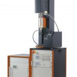
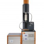
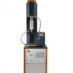
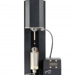
The DynTHERM TGA is an advanced gravimetric instrument for high temperature and high pressure thermogravimetric analysis.
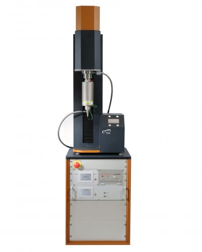
The DynTHERM TGA is an advanced gravimetric instrument featuring a patented* Magnetic Suspension Balance that enables measurement of weight changes of materials under high pressure, in the presence of a variety of gases, vapors, or steam, from room temperature to 1700°C. A flexible selection of gas & vapor dosing and blending devices provide accurate control of the composition and the pressure of the reaction atmosphere. Designed and built with over 20 years of experience and field proven by hundreds of customers, the Rubotherm Series DynTHERM TGA offers the widest available temperature and pressure range of all high pressure gravimetric analyzers and represents the industry standard for application relevant analysis.
* German Patent no. 10 2009 009 204.8
Features and Benefits:
- Non-contact sample weighing enables hermetic separation between sample cell and balance, eliminating risk of balance damage from reaction gases, pressure or temperature inside the sample cell
- Metallically sealed sample reactor cell enables measurements in corrosive, explosive, or toxic reaction gases, up to high temperatures, and from vacuum to high pressure
- Unique automatic sample decoupling enables taring of balance during experiments and provides unmatched long-term baseline stability for the most accurate measurements, without manual balance calibrations required by competitive devices
- Entire sample cell wetted by the reaction gases can be heated, preventing condensation of reaction gas vapors such as water vapor, CO2, ammonia etc., even at high pressures or humidity
- Sophisticated gas and vapor dosing, blending, and pressure controlling systems for precise reaction atmosphere control with integrated gas sampling for evolved gas analysis
- The large dynamic weighing range and sample volume allows measurements with representative, large and/or heavy samples
In the below table, the key specification for 8 different Magnetic Suspension Balance equipped Rubotherm Series DynTHERM TGA models are summarized.
For all models, operation under vacuum is possible. Gas dosing systems are equipped with two gas lines – each one with a separate MFC – as standard. Optionally, more gas lines can be added to the dosing system.
A special optional feature of all DynTHERM TGA models is the possibility of having a forced flow of the reaction atmosphere through the sample fixed bed. This is proven to be an extremely useful option for catalyst research, since the real operating conditions of the catalyst sample can be realized in the DynTHERM.
| Model |
Max. Sample Temperature | Maximum Pressure | Weighing Resolution | Weighing Range / Sample Mass | Reaction Atmosphere |
|---|---|---|---|---|---|
| 1100-1 , LP-G | 1100°C | 1 bar | 10 µg | 20 g / 25 g | Pure Gas & Gas Blends (of up to 5 gases) |
| 1700-1 , LP-G | 1700°C | 1 bar | 10 µg | 20 g / 25 g | Pure Gas & Gas Blends (of up to 5 gases) |
| 1100-50 , HP-G 1100-50 , HP-G+V |
1100°C | 50 bar* | 10 µg | 20 g / 25 g | Pure Gas & Gas Blends (of up to 5 gases) Pure Gas & Gas Blends & Gas and steam Blends (of up to 5 gases and 1 steam) |
| 1500-50 , HP-G 1500-50 , HP-G+V |
1500°C | 50 bar* | 10 µg | 20 g / 25 g | Pure Gas & Gas Blends (of up to 5 gases) Pure Gas & Gas Blends & Gas and steam Blends (of up to 5 gases and 1 steam) |
*Maximum pressure is temperature dependent
Please consult your local TA technical sales representative to get further information about the Rubotherm Series DynTHERM TGA instruments.
Magnetic Suspension Balance
Unique Magnetic Suspension Balance Technology
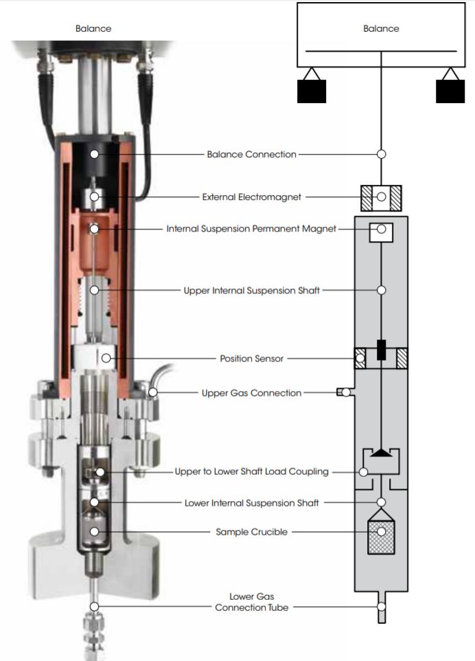
At the heart of every Rubotherm Series instrument is the patented Magnetic Suspension Balance (MSB), which weighs a sample in a closed reactor cell with an external microbalance. This is realized by means of a magnetic suspension coupling that transmits the weight force through the wall of the sample cell.
In this design, a permanent suspension magnet is attached at the top of an upper internal suspension shaft. A lower internal suspension shaft is connected to a crucible holding a sample material. Between the upper and lower suspension shafts is a load coupling mechanism. The upper and lower shafts and the sample crucible are enclosed
within the sample cell.
An external electromagnet is controlled to attract the internal permanent magnet. This raises the internal suspension magnet and engages the load coupling and, as a result, raises the sample crucible. The electromagnet control continues to apply attractive force until the system reaches a constant measuring point height.
The weight of the sample in the cell is determined by the external microbalance, to which the electromagnet is connected, with high resolution and accuracy.
Automatic Sample Decoupling Feature (ASD)
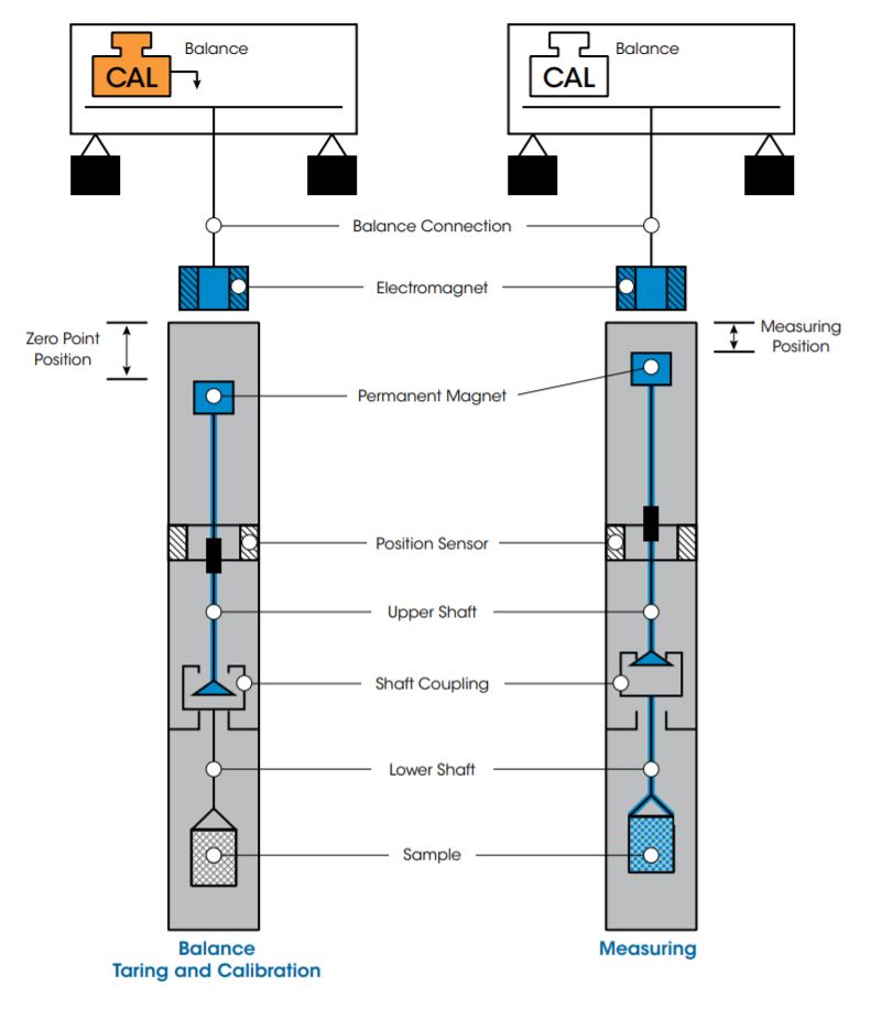
Automatic Sample Decoupling Feature (ASD)
At the start of any gravimetric experiment, the balance is automatically tared and calibrated to establish a “zero-point” for the weight measurement. This zero-point is the value used for all subsequent measurements. However, as experiment time frames can vary from hours to weeks, the ability to accurately measure small weight changes over extended times can be diminished by drift in the zero-point. Drift is typically due to external factors such as fluctuations in laboratory temperature and air pressure or humidity.
Attempts to improve signal accuracy have traditionally been to conduct empty crucible baseline runs and subtracting them from the sample run. This method is not ideal as it doubles experiment times, and is inherently flawed as no two experiments are ever exactly the same. Only TA’s DynTHERM TGA, with patented MSB technology, provides the unique Automatic Sample Decoupling (ASD) feature for real-time drift corrections, increasing weight accuracy to previously unattainable levels, especially for long-term measurements.
How ASD Works:
As shown in the figure above, the MSB design includes a shaft load coupling. When the electromagnet is energized, it attracts the permanent magnet that is connected to the upper shaft. The upper shaft lifts upward, engages the coupling, and raises the crucible to the measuring point to make the weight measurement. At any time during the experiment, the permanent suspension magnet can be moved downward to decouple from the sample crucible. During this downward movement, the shaft load coupling is placed at rest on a support. The suspension magnet remains in a free-floating state, transferring only its weight to the balance. By moving to this new zero-point position corresponding to an unloaded balance, taring and calibrating are possible during measurements, even under process conditions (pressure, temperature) in the sample cell. This unique automatic software-controlled calibration of the balance, during measurements, is available ONLY on TA Instruments’ commercial gravimetric analyzer.
Forced Flow Through Bulk Material Beds Option
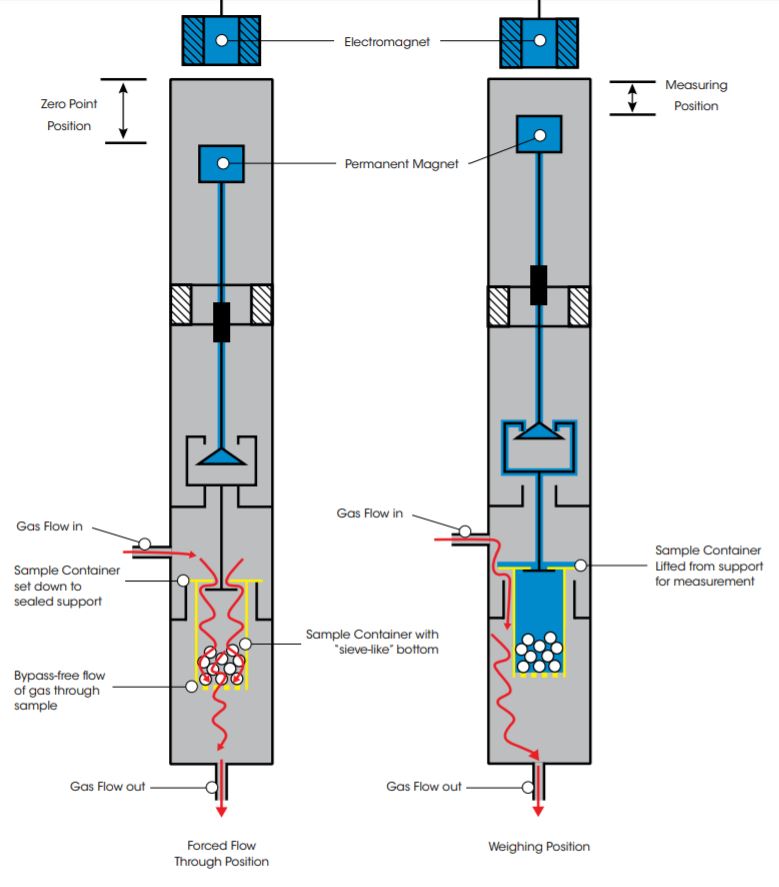
Forced Gas Flow Through Bulk Material Beds
The DynTHERM TGA features a unique forced gas flow through option for applications that require a forced flow of reaction gas through the sample material bed. This capability, which enables mimicking real process conditions of a material in a bulk reactor, is demonstrated in the schematic above.
For forced gas flow measurements, the sample is placed in a container with a “sieve-like” bottom and a flanged lid with an opening in the center. When the balance is in the zero-point position, the flange of the sample container rests on top of a bypass free support. The sample container is disconnected from the balance and reaction gas is forced to flow into the container from the opening at its top, passing through the sample to finally exit through the “sieve-like” bottom.
The sample is weighed over specified intervals of time by raising the MSB into measuring position, which lifts the sample container from the supports. Once the weight measurement is completed, the sample container is returned to the rest position to start the process again.
Environmental Reactors
Environmental Reactors
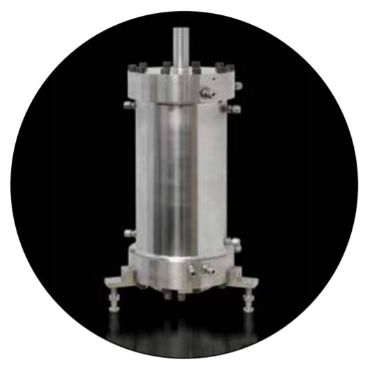
The DynTHERM TGA instruments are equipped with low or high pressure sample cells with electrical heaters for accurate temperature control under all pressure and gas flow conditions.
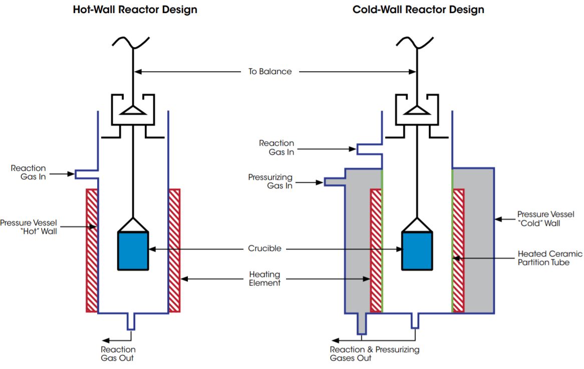
Cold wall reactor design
Installation of the electrical heater into a pressure vessel – the cold wall reactor setup – allows the use of only corrosion-resistant ceramic materials in the high temperature zone. The cold wall heaters can be applied using very corrosive reaction atmospheres in a temperature range up to 1500°C* and at pressures up to 50 bar*.
Hot wall reactor design
Hot wall reactors are sample cells made of temperature and corrosion-resistant ceramics or special metal alloys. The temperature of the sample in the reactor is controlled by an outside electrical heater that heats the sample through the wall. The hot wall reactors provide especially large temperature constant zones for measurements in the temperature range up to 1700°C*.
Temperature control
Sample temperature is measured by a thermocouple directly adjacent to the sample inside the reaction gas. Furnace temperature and temperatures in other parts of the reactor are measured with additional thermocouples. A fast PID temperature controller realizes precise temperature control of the sample under all operating conditions.
* Specifications are model-dependent
Gas & Vapor Dosing Systems
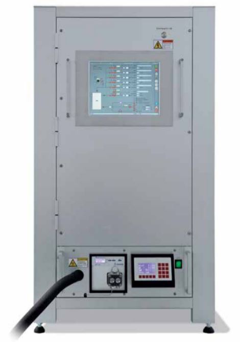
Gas & Vapor Dosing, Blending, and Pressure Control Systems
The accuracy of TGA measurements rely on accurate control of the pressure and the composition of the reaction atmosphere. The DynTHERM TGA features sophisticated gas & vapor dosing and blending systems with pressure controllers that ensure the highest data quality while providing flexibility to address the widest range of applications. These systems provide a continuous flow of pure reaction gas, a gas mixture, or gas and vapor mixture with controlled composition to the sample reactor cell of the TGA. A dynamic backpressure controller in the outlet flow maintains pressure with the highest stability and precision.
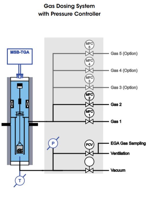
Each dosing system includes two mass flow controllers (MFC 1, MFC 2) for dosing pure gas or blending gas mixtures and dosing into the TGA reactor, an accurate pressure sensor (P), a PID controller, a pressure controlling valve (PCV) in the gas flow at the reactor exit, and a gas sampling connection for evolved gas analysis (EGA). Additional gas lines with mass flow controllers are optional.
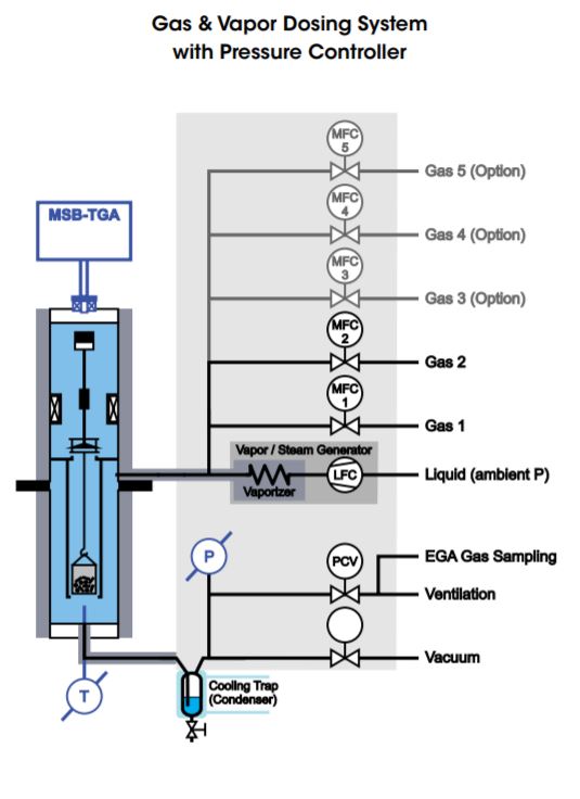
Gas and Vapor (steam) Dosing Systems are additionally equipped with a vapor/steam generator consisting of a liquid compressing and flow control pump (LFC) for dosing a controlled flow of liquid into a vaporizer in which the steam is generated. The steam is then mixed with the gas flow(s) coming from the MFC’s and flows into the TGA reactor through heated transfer lines.
Pyrolysis and Gasification
Pyrolysis and Gasification
Coal, biomass, waste, and other organic materials are gasified for energy utilization or as alternative feedstock. Such processes can be measured under application-relevant conditions in the DynTHERM high pressure TGA instruments configured with gas and steam dosing. The first step in a gasification processes is pyrolysis of the raw material, where while heating the organic material in an inert atmosphere (eg. N2 or Ar), volatile components (water, hydrocarbons, tar) are evaporated and char is generated. Gasifying this carbon-rich char as a second reaction step requires a gasifying agent, typically steam. The superheated steam and the carbon generate gases according to the following main reaction:
H2O + C → CO + H2
In parallel, additional gases are products of conversions and side reactions:
mC + nH → CmHn | CO + H2O → H2 + CO2 | CO + 3H2 → CH4 + H2O
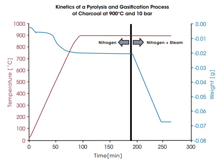
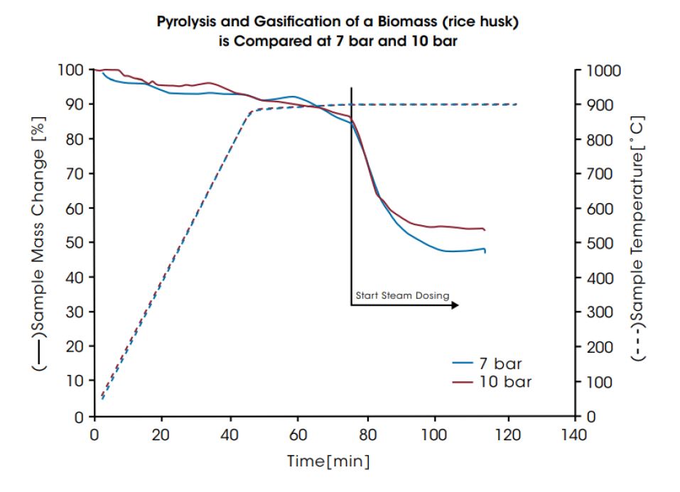
Because the process reaction kinetics depend on the reaction conditions and the raw material, the composition and the pressure of the gases generated will vary. DynTHERM TGA instruments allow optimization of operating conditions for a given raw material. Additionally, they can be equipped with a mass spectrometer for evolved gas analysis. In the first diagram below, the kinetics of a pyrolysis and gasification process of charcoal at 900°C and 10 bar is displayed. In the last diagram, the pyrolysis and gasification of a biomass (rice husk) is compared for 7 bar and 10 bar. In both experiments the pyrolysis takes place at the beginning during heating the sample in inert gas. After pyrolysis, gasification starts when steam is injected and leads to the main mass change of the sample materials.
Catalyst Coking
Catalyst Coking
Catalyst deactivation due to coking is an unavoidable technological and economic problem in petroleum refining and in the petrochemical industry. Coking occurs when hydrocarbon-rich feed gases react with the catalyst, and solid carbon deposits build up on the surface of the catalyst. These carbon-containing deposits can quickly and easily reach a level where they disturb the process. For example, they may create pressure drop problems or block off catalytic sites. Methods to prevent or delay the catalyst deactivation include the modification of catalyst surface composition and/or changing of the reaction environment (pressure, temperature, and feed gas composition). After deactivation, alternative regeneration by burning off carbon residues can be studied.
Process optimization of catalyst decay and/or regeneration is an engineering problem that requires a knowledge of the catalyst deactivation kinetics. DynTHERM TGA instruments enable studying the weight of catalyst and the development of coking under realistic refinery operating conditions.
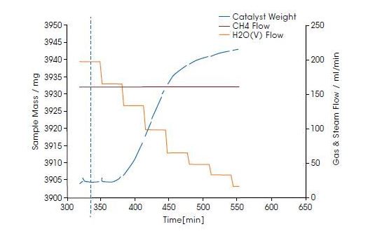
The diagram below shows an example of the build up of coke on a catalytic material at 20 bar and 650°C in a reactive atmosphere of CH4 and steam. The steam partial pressure is reduced stepwise, which leads to the mass increase of the catalyst material due to coke formation. The maximum specific coke deposition rate calculated from the blue curve in the figure, in milligrams per grams of catalyst per second, is 0.32 mg g-1 s-1.
In the lower figure, the starting of coking on a commercial catalyst at 700°C and 20 bar is measured in a steam / CH4 mixture at flow rate of 70 ml/min. An increase in the coking rate was observed when the CH4 flow rate was increased to 73 ml/min, with a constant steam flow rate.

Corrosion and Oxidation
Corrosion and Oxidation
Better corrosion resistance of materials is key for improving the efficiency of many technical processes. For example, the efficiency of gas or steam turbines and jet engines is directly related to their ability to resist corrosion at maximum operation temperature.
DynTHERM TGA instruments offer corrosion-resistant reactors capable of measuring materials in corrosive atmospheres at high temperature. For many materials, the instrument can accommodate large samples (by both mass and volume), which is advantageous as the resultant mass change caused by the corrosion tends to be very small. In addition, high temperature corrosion is usually a slow process. The ability of the patented MSB to tare and calibrate the balance during measurement enables for the most accurate long-term corrosion studies.
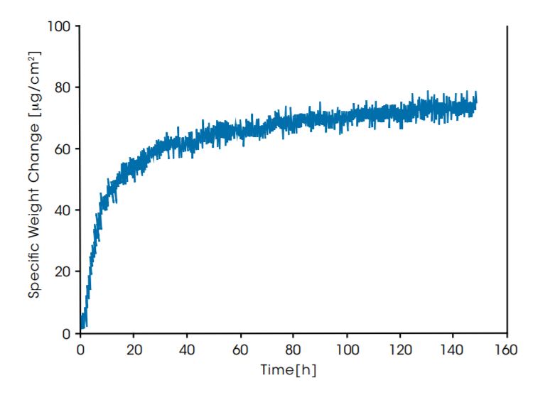
The diagram below shows a long-term study on the mass increase of a diamond-coated titanium sample. The weight gain is caused by oxidation of the sample in pure Oxygen at 600°C. The total mass change here is about 140 μg over 6 days.
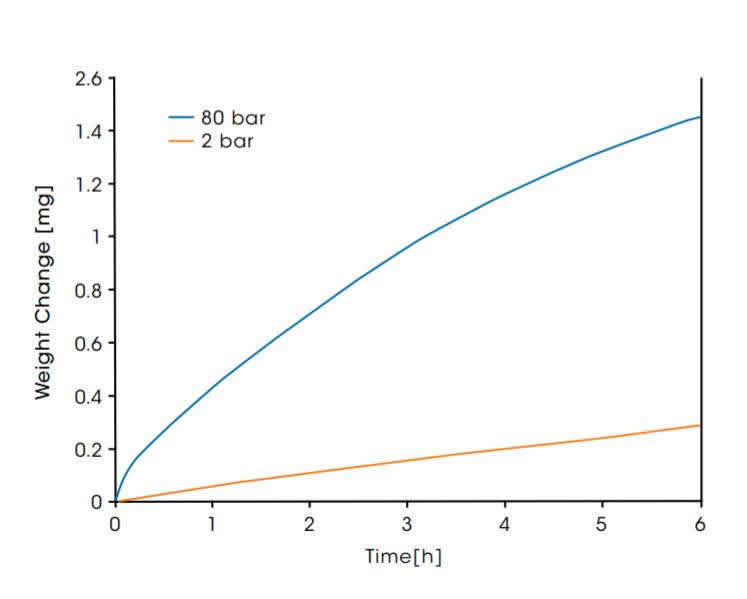
In the diagram below, the weight gain of a high performance Inconel®* alloy C-276 in air at 1000°C and at two different pressures of 2 and 80 bar is shown. The alloy samples had a starting mass of 89 mg and a surface area of 0.47 cm2. The weight increases observed are a result of oxidation of the metal alloy surface. The corrosion rate is 5 times higher at high pressure. The weight change at high pressure seems to approach saturation which indicates the formation of a stable oxidic layer. The surface area specific oxidative weight gain after 6 hours was 610 μg/cm2 at 2 bar and 3080 μg/cm2 at 80 bar.
Chemical Looping
Chemical Looping
The combustion of fossil fuels in nearly pure oxygen, rather than air, presents an opportunity to simplify carbon dioxide capture in power plant applications. Chemical looping systems supply oxygen internal to the process, eliminating large capital and operating costs associated with pre-combustion oxygen generation. Chemical looping combustion (CLC) is considered a transformational technology with the potential to meet program cost and performance goals for CO2 reduced electricity generation from fossil fuels.
In CLC systems, oxygen is introduced via oxidation-reduction cycling of an oxygen carrier material. The oxygen carrier is usually a solid, metal-based compound. In a typical CLC process, combustion is split into separate reduction and oxidation reactors as shown in the schematic below. The metal oxide supplies oxygen for combustion and is reduced by the fuel in the fuel reactor, which is operated at elevated temperature.
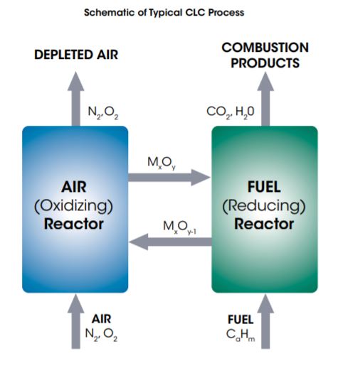
This reaction can be exothermic or endothermic, depending on the fuel and the oxygen carrier. The combustion product from the fuel reactor is a highly concentrated CO2 and H2O stream that can be purified, compressed, and sent to storage for later beneficial use. The reduced oxygen carrier is then sent to the air reactor, also operated at elevated temperature, where it is regenerated to its oxidized state. The air reactor produces a hot spent air stream, which is used to produce steam to drive a power generating turbine. Then the oxygen carrier is returned to the fuel reactor, restarting the reduction-oxidation cycle.
Current CLC R&D efforts are focused on developing oxygen carrier materials with sufficient oxygen capacity and durability to withstand harsh CLC environments. DynTHERM TGA instruments allow measurements of the weight of oxygen carrier materials under realistic operating conditions, including cycling the materials many times through oxidation and reduction cycles at high temperatures and pressures, while alternating between oxidizing and reducing (flammable) gases, and/or steam.
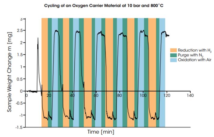
The diagram below shows the result of cycling of an oxygen carrier material at 10 bar and 800°C. The material is reduced in humidified H2 and oxidized in dry air. The weight changes recorded in the redox cycles are fairly constant and amount to approximately 9% of the starting sample weight.
- Description
-
The DynTHERM TGA is an advanced gravimetric instrument featuring a patented* Magnetic Suspension Balance that enables measurement of weight changes of materials under high pressure, in the presence of a variety of gases, vapors, or steam, from room temperature to 1700°C. A flexible selection of gas & vapor dosing and blending devices provide accurate control of the composition and the pressure of the reaction atmosphere. Designed and built with over 20 years of experience and field proven by hundreds of customers, the Rubotherm Series DynTHERM TGA offers the widest available temperature and pressure range of all high pressure gravimetric analyzers and represents the industry standard for application relevant analysis.
* German Patent no. 10 2009 009 204.8
- Features
-
Features and Benefits:
- Non-contact sample weighing enables hermetic separation between sample cell and balance, eliminating risk of balance damage from reaction gases, pressure or temperature inside the sample cell
- Metallically sealed sample reactor cell enables measurements in corrosive, explosive, or toxic reaction gases, up to high temperatures, and from vacuum to high pressure
- Unique automatic sample decoupling enables taring of balance during experiments and provides unmatched long-term baseline stability for the most accurate measurements, without manual balance calibrations required by competitive devices
- Entire sample cell wetted by the reaction gases can be heated, preventing condensation of reaction gas vapors such as water vapor, CO2, ammonia etc., even at high pressures or humidity
- Sophisticated gas and vapor dosing, blending, and pressure controlling systems for precise reaction atmosphere control with integrated gas sampling for evolved gas analysis
- The large dynamic weighing range and sample volume allows measurements with representative, large and/or heavy samples
- Specifications
-
In the below table, the key specification for 8 different Magnetic Suspension Balance equipped Rubotherm Series DynTHERM TGA models are summarized.
For all models, operation under vacuum is possible. Gas dosing systems are equipped with two gas lines – each one with a separate MFC – as standard. Optionally, more gas lines can be added to the dosing system.
A special optional feature of all DynTHERM TGA models is the possibility of having a forced flow of the reaction atmosphere through the sample fixed bed. This is proven to be an extremely useful option for catalyst research, since the real operating conditions of the catalyst sample can be realized in the DynTHERM.
Model
Max. Sample Temperature Maximum Pressure Weighing Resolution Weighing Range / Sample Mass Reaction Atmosphere 1100-1 , LP-G 1100°C 1 bar 10 µg 20 g / 25 g Pure Gas & Gas Blends (of up to 5 gases) 1700-1 , LP-G 1700°C 1 bar 10 µg 20 g / 25 g Pure Gas & Gas Blends (of up to 5 gases) 1100-50 , HP-G
1100-50 , HP-G+V1100°C 50 bar* 10 µg 20 g / 25 g Pure Gas & Gas Blends (of up to 5 gases)
Pure Gas & Gas Blends & Gas and steam Blends (of up to 5 gases and 1 steam)1500-50 , HP-G
1500-50 , HP-G+V1500°C 50 bar* 10 µg 20 g / 25 g Pure Gas & Gas Blends (of up to 5 gases)
Pure Gas & Gas Blends & Gas and steam Blends (of up to 5 gases and 1 steam)*Maximum pressure is temperature dependent
Please consult your local TA technical sales representative to get further information about the Rubotherm Series DynTHERM TGA instruments.
- Technology
-
Magnetic Suspension Balance

Unique Magnetic Suspension Balance Technology
At the heart of every Rubotherm Series instrument is the patented Magnetic Suspension Balance (MSB), which weighs a sample in a closed reactor cell with an external microbalance. This is realized by means of a magnetic suspension coupling that transmits the weight force through the wall of the sample cell.
In this design, a permanent suspension magnet is attached at the top of an upper internal suspension shaft. A lower internal suspension shaft is connected to a crucible holding a sample material. Between the upper and lower suspension shafts is a load coupling mechanism. The upper and lower shafts and the sample crucible are enclosed
within the sample cell.An external electromagnet is controlled to attract the internal permanent magnet. This raises the internal suspension magnet and engages the load coupling and, as a result, raises the sample crucible. The electromagnet control continues to apply attractive force until the system reaches a constant measuring point height.
The weight of the sample in the cell is determined by the external microbalance, to which the electromagnet is connected, with high resolution and accuracy.
Automatic Sample Decoupling Feature (ASD)

Automatic Sample Decoupling Feature (ASD)
At the start of any gravimetric experiment, the balance is automatically tared and calibrated to establish a “zero-point” for the weight measurement. This zero-point is the value used for all subsequent measurements. However, as experiment time frames can vary from hours to weeks, the ability to accurately measure small weight changes over extended times can be diminished by drift in the zero-point. Drift is typically due to external factors such as fluctuations in laboratory temperature and air pressure or humidity.
Attempts to improve signal accuracy have traditionally been to conduct empty crucible baseline runs and subtracting them from the sample run. This method is not ideal as it doubles experiment times, and is inherently flawed as no two experiments are ever exactly the same. Only TA’s DynTHERM TGA, with patented MSB technology, provides the unique Automatic Sample Decoupling (ASD) feature for real-time drift corrections, increasing weight accuracy to previously unattainable levels, especially for long-term measurements.
How ASD Works:
As shown in the figure above, the MSB design includes a shaft load coupling. When the electromagnet is energized, it attracts the permanent magnet that is connected to the upper shaft. The upper shaft lifts upward, engages the coupling, and raises the crucible to the measuring point to make the weight measurement. At any time during the experiment, the permanent suspension magnet can be moved downward to decouple from the sample crucible. During this downward movement, the shaft load coupling is placed at rest on a support. The suspension magnet remains in a free-floating state, transferring only its weight to the balance. By moving to this new zero-point position corresponding to an unloaded balance, taring and calibrating are possible during measurements, even under process conditions (pressure, temperature) in the sample cell. This unique automatic software-controlled calibration of the balance, during measurements, is available ONLY on TA Instruments’ commercial gravimetric analyzer.
Forced Flow Through Bulk Material Beds Option

Forced Gas Flow Through Bulk Material Beds
The DynTHERM TGA features a unique forced gas flow through option for applications that require a forced flow of reaction gas through the sample material bed. This capability, which enables mimicking real process conditions of a material in a bulk reactor, is demonstrated in the schematic above.
For forced gas flow measurements, the sample is placed in a container with a “sieve-like” bottom and a flanged lid with an opening in the center. When the balance is in the zero-point position, the flange of the sample container rests on top of a bypass free support. The sample container is disconnected from the balance and reaction gas is forced to flow into the container from the opening at its top, passing through the sample to finally exit through the “sieve-like” bottom.
The sample is weighed over specified intervals of time by raising the MSB into measuring position, which lifts the sample container from the supports. Once the weight measurement is completed, the sample container is returned to the rest position to start the process again.
Environmental Reactors
Environmental Reactors

The DynTHERM TGA instruments are equipped with low or high pressure sample cells with electrical heaters for accurate temperature control under all pressure and gas flow conditions.
Cold wall reactor design
Installation of the electrical heater into a pressure vessel – the cold wall reactor setup – allows the use of only corrosion-resistant ceramic materials in the high temperature zone. The cold wall heaters can be applied using very corrosive reaction atmospheres in a temperature range up to 1500°C* and at pressures up to 50 bar*.
Hot wall reactor design
Hot wall reactors are sample cells made of temperature and corrosion-resistant ceramics or special metal alloys. The temperature of the sample in the reactor is controlled by an outside electrical heater that heats the sample through the wall. The hot wall reactors provide especially large temperature constant zones for measurements in the temperature range up to 1700°C*.

Temperature control
Sample temperature is measured by a thermocouple directly adjacent to the sample inside the reaction gas. Furnace temperature and temperatures in other parts of the reactor are measured with additional thermocouples. A fast PID temperature controller realizes precise temperature control of the sample under all operating conditions.
* Specifications are model-dependent
Gas & Vapor Dosing Systems

Gas & Vapor Dosing, Blending, and Pressure Control Systems
The accuracy of TGA measurements rely on accurate control of the pressure and the composition of the reaction atmosphere. The DynTHERM TGA features sophisticated gas & vapor dosing and blending systems with pressure controllers that ensure the highest data quality while providing flexibility to address the widest range of applications. These systems provide a continuous flow of pure reaction gas, a gas mixture, or gas and vapor mixture with controlled composition to the sample reactor cell of the TGA. A dynamic backpressure controller in the outlet flow maintains pressure with the highest stability and precision.
Each dosing system includes two mass flow controllers (MFC 1, MFC 2) for dosing pure gas or blending gas mixtures and dosing into the TGA reactor, an accurate pressure sensor (P), a PID controller, a pressure controlling valve (PCV) in the gas flow at the reactor exit, and a gas sampling connection for evolved gas analysis (EGA). Additional gas lines with mass flow controllers are optional.

Gas and Vapor (steam) Dosing Systems are additionally equipped with a vapor/steam generator consisting of a liquid compressing and flow control pump (LFC) for dosing a controlled flow of liquid into a vaporizer in which the steam is generated. The steam is then mixed with the gas flow(s) coming from the MFC’s and flows into the TGA reactor through heated transfer lines.

- Applications
-
Pyrolysis and Gasification
Pyrolysis and Gasification
Coal, biomass, waste, and other organic materials are gasified for energy utilization or as alternative feedstock. Such processes can be measured under application-relevant conditions in the DynTHERM high pressure TGA instruments configured with gas and steam dosing. The first step in a gasification processes is pyrolysis of the raw material, where while heating the organic material in an inert atmosphere (eg. N2 or Ar), volatile components (water, hydrocarbons, tar) are evaporated and char is generated. Gasifying this carbon-rich char as a second reaction step requires a gasifying agent, typically steam. The superheated steam and the carbon generate gases according to the following main reaction:
H2O + C → CO + H2
In parallel, additional gases are products of conversions and side reactions:
mC + nH → CmHn | CO + H2O → H2 + CO2 | CO + 3H2 → CH4 + H2O
Because the process reaction kinetics depend on the reaction conditions and the raw material, the composition and the pressure of the gases generated will vary. DynTHERM TGA instruments allow optimization of operating conditions for a given raw material. Additionally, they can be equipped with a mass spectrometer for evolved gas analysis. In the first diagram below, the kinetics of a pyrolysis and gasification process of charcoal at 900°C and 10 bar is displayed. In the last diagram, the pyrolysis and gasification of a biomass (rice husk) is compared for 7 bar and 10 bar. In both experiments the pyrolysis takes place at the beginning during heating the sample in inert gas. After pyrolysis, gasification starts when steam is injected and leads to the main mass change of the sample materials.


Catalyst Coking
Catalyst Coking
Catalyst deactivation due to coking is an unavoidable technological and economic problem in petroleum refining and in the petrochemical industry. Coking occurs when hydrocarbon-rich feed gases react with the catalyst, and solid carbon deposits build up on the surface of the catalyst. These carbon-containing deposits can quickly and easily reach a level where they disturb the process. For example, they may create pressure drop problems or block off catalytic sites. Methods to prevent or delay the catalyst deactivation include the modification of catalyst surface composition and/or changing of the reaction environment (pressure, temperature, and feed gas composition). After deactivation, alternative regeneration by burning off carbon residues can be studied.
Process optimization of catalyst decay and/or regeneration is an engineering problem that requires a knowledge of the catalyst deactivation kinetics. DynTHERM TGA instruments enable studying the weight of catalyst and the development of coking under realistic refinery operating conditions.
The diagram below shows an example of the build up of coke on a catalytic material at 20 bar and 650°C in a reactive atmosphere of CH4 and steam. The steam partial pressure is reduced stepwise, which leads to the mass increase of the catalyst material due to coke formation. The maximum specific coke deposition rate calculated from the blue curve in the figure, in milligrams per grams of catalyst per second, is 0.32 mg g-1 s-1.

In the lower figure, the starting of coking on a commercial catalyst at 700°C and 20 bar is measured in a steam / CH4 mixture at flow rate of 70 ml/min. An increase in the coking rate was observed when the CH4 flow rate was increased to 73 ml/min, with a constant steam flow rate.

Corrosion and Oxidation
Corrosion and Oxidation
Better corrosion resistance of materials is key for improving the efficiency of many technical processes. For example, the efficiency of gas or steam turbines and jet engines is directly related to their ability to resist corrosion at maximum operation temperature.
DynTHERM TGA instruments offer corrosion-resistant reactors capable of measuring materials in corrosive atmospheres at high temperature. For many materials, the instrument can accommodate large samples (by both mass and volume), which is advantageous as the resultant mass change caused by the corrosion tends to be very small. In addition, high temperature corrosion is usually a slow process. The ability of the patented MSB to tare and calibrate the balance during measurement enables for the most accurate long-term corrosion studies.
The diagram below shows a long-term study on the mass increase of a diamond-coated titanium sample. The weight gain is caused by oxidation of the sample in pure Oxygen at 600°C. The total mass change here is about 140 μg over 6 days.

In the diagram below, the weight gain of a high performance Inconel®* alloy C-276 in air at 1000°C and at two different pressures of 2 and 80 bar is shown. The alloy samples had a starting mass of 89 mg and a surface area of 0.47 cm2. The weight increases observed are a result of oxidation of the metal alloy surface. The corrosion rate is 5 times higher at high pressure. The weight change at high pressure seems to approach saturation which indicates the formation of a stable oxidic layer. The surface area specific oxidative weight gain after 6 hours was 610 μg/cm2 at 2 bar and 3080 μg/cm2 at 80 bar.

Chemical Looping
Chemical Looping
The combustion of fossil fuels in nearly pure oxygen, rather than air, presents an opportunity to simplify carbon dioxide capture in power plant applications. Chemical looping systems supply oxygen internal to the process, eliminating large capital and operating costs associated with pre-combustion oxygen generation. Chemical looping combustion (CLC) is considered a transformational technology with the potential to meet program cost and performance goals for CO2 reduced electricity generation from fossil fuels.
In CLC systems, oxygen is introduced via oxidation-reduction cycling of an oxygen carrier material. The oxygen carrier is usually a solid, metal-based compound. In a typical CLC process, combustion is split into separate reduction and oxidation reactors as shown in the schematic below. The metal oxide supplies oxygen for combustion and is reduced by the fuel in the fuel reactor, which is operated at elevated temperature.

This reaction can be exothermic or endothermic, depending on the fuel and the oxygen carrier. The combustion product from the fuel reactor is a highly concentrated CO2 and H2O stream that can be purified, compressed, and sent to storage for later beneficial use. The reduced oxygen carrier is then sent to the air reactor, also operated at elevated temperature, where it is regenerated to its oxidized state. The air reactor produces a hot spent air stream, which is used to produce steam to drive a power generating turbine. Then the oxygen carrier is returned to the fuel reactor, restarting the reduction-oxidation cycle.
Current CLC R&D efforts are focused on developing oxygen carrier materials with sufficient oxygen capacity and durability to withstand harsh CLC environments. DynTHERM TGA instruments allow measurements of the weight of oxygen carrier materials under realistic operating conditions, including cycling the materials many times through oxidation and reduction cycles at high temperatures and pressures, while alternating between oxidizing and reducing (flammable) gases, and/or steam.
The diagram below shows the result of cycling of an oxygen carrier material at 10 bar and 800°C. The material is reduced in humidified H2 and oxidized in dry air. The weight changes recorded in the redox cycles are fairly constant and amount to approximately 9% of the starting sample weight.

DynTHERM TGA Photo Gallery
