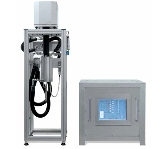
The IsoSORP SA is an advanced gravimetric instrument featuring a patented* Magnetic Suspension Balance that enables sorption measurements under high pressure or vacuum environments.
Samples can be measured in the presence of a variety of gases or vapors over a wide temperature range covering -196°C to 400°C. A flexible selection of dosing and blending devices provide accurate control of the composition and pressure of the reaction atmosphere. Designed and built with over 20 years of experience and field-proven by hundreds of customers, the Rubotherm Series IsoSORP SA offers the widest available pressure range of all gravimetric sorption analyzers, and represents the industry standard for application-relevant analysis.
* German Patent no. 10 2009 009 204.8
Features and Benefits:
- Non-contact sample weighing enables hermetic separation between sample cell and balance, eliminating risk of balance damage from reaction gases, pressure or temperature inside the sample cell
- Metallically sealed sample reactor cell enables measurements in corrosive, explosive, or toxic reaction gases, from cryogenic to high temperatures, and from vacuum to high pressure.
- Unique automatic sample decoupling enables taring of balance during experiments and provides unmatched long-term baseline stability for the most accurate measurements without manual balance calibrations required by competitive devices
- Entire sample cell wetted by the reaction gases can be heated, preventing condensation of reaction gas vapors such as water vapor, CO2, ammonia etc., even at high pressures or humidity
- Gravimetric measurement of the reaction gas density in the sample cell allows automatic and accurate buoyancy correction of the gravimetric data at all pressure and temperature conditions, as well as reaction gas compositions
- The large dynamic weighing range and sample volume allows measurements with representative, large and/or heavy samples
| Magnetic Suspension Balance (MSB) | Pressure[1] | Temperature | Dosing System Type | |||
| IsoSORP SA Model | Resolution (μg) | Mass Range (g) | Max. Pressure (bar) | Min (°C) | Max (°C) | |
| 400-150, S-G | 10 | 25 | 150 | RT | 400°C | Static Gas (S-G) |
| 400-150, S-G XR | 1 | 10 | 150 | RT | 400°C | |
| 400-150, S-G Cryo | 10 | 25 | 150 | 196°C[2] | 400°C | |
| 400-150, S-G LT | 10 | 25 | 150 | -20 | 400°C | |
| 400-150, S-G XR LT | 1 | 10 | 150 | -20 | 400°C | |
| 400-50, S-G+V | 10 | 25 | 50 | RT | 400°C | Static Gas & Vapor (S-G+V) |
| 400-50, S-G+V XR | 1 | 10 | 50 | RT | 400°C | |
| 400-150, S-SC | 10 | 25 | 150 | RT | 400°C | Static Sub-Critical Fuids and Gas (S-SC) |
| 400-150, S-SC LT | 10 | 25 | 150 | -20 | 400°C | |
| 150-150, S-SC Visi | 10 | 25 | 150 | RT | 150°C[4] | |
| 150-350, S-SC | 10 | 25 | 350 | RT | 150°C[3] | |
| 150-350, S-SC LT | 10 | 25 | 350 | -20 | 150°C[3] | |
| 150-350, S-SC Visi | 10 | 25 | 350 | RT | 150°C[4] | |
| 150-700, S-SC | 10 | 25 | 700 | RT | 150°C[4] | |
| 400-50, F-G | 10 | 25 | 50 | RT | 400°C | Flow Gas (F-G) |
| 400-50, F-G XR | 1 | 10 | 50 | RT | 400°C | |
| 400-150, F-G | 10 | 25 | 150 | RT | 400°C | |
| 400-150, F-G XR | 1 | 10 | 150 | RT | 400°C | |
| 400-50, F-G+V | 10 | 25 | 50 | RT | 400°C | Flow Gas & Vapor (F-G+V) |
| 400-50, F-G+V XR | 1 | 10 | 50 | RT | 400°C | |
| 400-150, F-G+V | 10 | 25 | 150 | RT | 400°C | |
[1] Vacuum specification: 0.0075 Torr possible (requires adequate vacuum pump)
[2] Sample can be cooled to -196°C or -186°C, continuous temperature controlling range -150°C to 400°C
[3] Up to 400°C at pressures not exceeding 150 bar
[4] Not equipped with electrical heater
Unique Magnetic Suspension Balance Technology
Unique Magnetic Suspension Balance Technology
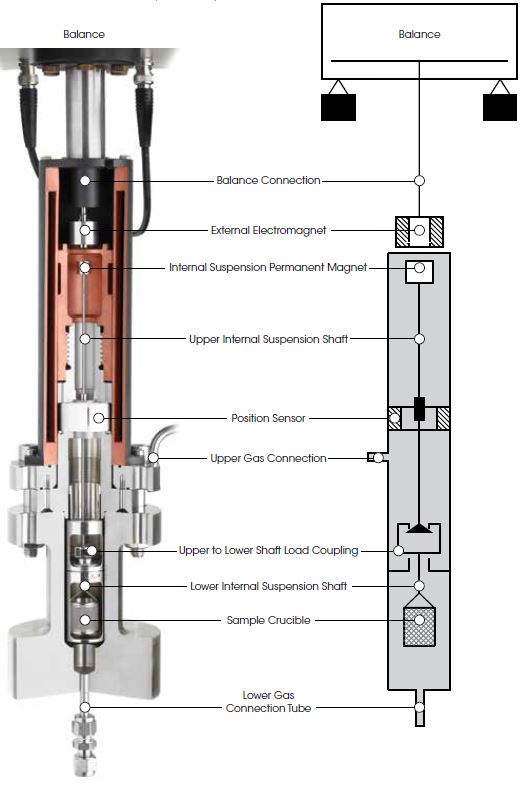
At the heart of every Rubotherm instrument is the patented Magnetic Suspension Balance (MSB), which weighs a sample in a closed reactor cell with an external microbalance. This is realized by means of a magnetic suspension coupling that transmits the weight force through the wall of the sample cell.
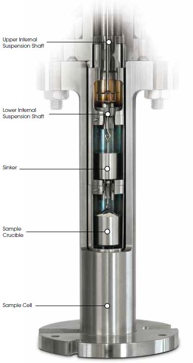
In this design, a permanent suspension magnet is attached at the top of an upper internal suspension shaft. A lower internal suspension shaft is connected to a crucible holding a sample material. Between the upper and lower suspension shafts is a load coupling mechanism. The upper and lower shafts and the sample crucible are enclosed within the sample cell.
An external electromagnet is controlled to attract the internal permanent magnet. This raises the internal suspension magnet and engages the load coupling and, as a result, raises the sample crucible. The electromagnet control continues to apply attractive force until the system reaches a constant measuring point height.
The weight of the sample in the cell is determined by the external microbalance, to which the electromagnet is connected, with high resolution and accuracy.
Automatic Sample Decoupling Feature (ASD)
Automatic Sample Decoupling Feature (ASD)
At the start of any gravimetric experiment, the balance is automatically tared and calibrated to establish a “zero-point” for the weight measurement. This zero-point is the value used for all subsequent measurements. However, as experiment time frames can vary from hours to weeks, the ability to accurately measure small weight changes over extended times can be diminished by drift in the zero-point. Drift is typically due to external factors such as fluctuations in laboratory temperature and air pressure or humidity.
Attempts to improve signal accuracy have traditionally been to conduct empty crucible baseline runs and subtracting them from the sample run. This method is not ideal as it doubles experiment times, and is inherently flawed as no two experiments are ever exactly the same. Only TA’s IsoSORP SA, with patented MSB technology, provides the unique Automatic Sample Decoupling (ASD) feature for real-time drift corrections, increasing weight accuracy to previously unattainable levels, especially for long-term measurements.
How ASD Works:
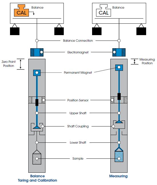
As shown in the figure above, the MSB design includes a shaft load coupling. When the electromagnet is energized, it attracts the permanent magnet that is connected to the upper shaft. The upper shaft lifts upward, engages the coupling, and raises the crucible to the measuring point to make the weight measurement. At any time during the experiment, the permanent suspension magnet can be moved downward to decouple from the sample crucible.
During this downward movement, the shaft load coupling is placed at rest on a support. The suspension magnet remains in a free-floating state, transferring only its weight to the balance. By moving to this new zero-point position corresponding to an unloaded balance, taring and calibrating are possible during measurements, even under process conditions (pressure, temperature) in the sample cell. This unique automatic software-controlled calibration of the balance, during measurements, is available ONLY on TA Instruments’ commercial gravimetric analyzer.
Dual-Sample Weight and Gas Phase Density Measurements
Dual-Sample Weight and Gas Phase Density Measurements
The IsoSORP can be configured with a second load coupling and sample position, enabling the weight measurement of two samples during a single experiment. This function can be used for comparative measurements of two samples (e. g. comparison of reactive and reference samples), or for determination of both sorption and density of the gaseous atmosphere in the reactor.
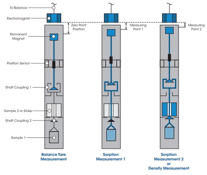
The second coupling and sample position creates a total of three vertical positions to which the MSB is controlled. These include the Zero Point, or Tare position, Measuring Point 1, and Measuring Point 2. This capability is demonstrated through a series of schematic diagrams in the figure above follows:
- Zero Point Position: Only the permanent magnet is suspended in order to tare and/or calibrate the microbalance.
- Measuring Point 1: The permanent magnet is raised, engaging the first coupling where the weight of the first reactive sample (adsorbent, catalyst, organic materials, etc.) is determined for sorption measurement 1.
- Measuring Point 2: With the first coupling engaged, the permanent magnet is raised further to engage the second coupling, lifting and weighing the combined mass of both samples. By subtracting the weight measured in Measuring Point 1 from the combined weight, the weight of the second sample is determined for sorption measurement 2. In the case of determining the density of the fluid phase in the reactor, an inert sinker with known volume serves as the second sample. Using the Archimedes principle, the density of the gas phase in the reactor is precisely determined from the buoyancy force acting on the sinker.
Automatic Buoyancy Correction for Unrivaled True Mass Accuracy
Automatic Buoyancy Correction for Unrivaled True Mass Accuracy
In sorption measurements, a sample is exposed to a reaction gas at controlled temperature and pressure. Usually the pressure is incremented in a stepwise fashion, and the sample mass changes due to adsorption or absorption of the gas in/on the sample are measured. Along with sample mass, gas phase density changes with pressure and/or temperature, resulting in a change in buoyancy effect acting on the sample. The buoyancy effect is the mass of the reaction gas atmosphere which is displaced by the sample, resulting in the ”apparent” loss of sample mass or an “apparent sample mass” measurement as observed by the balance. The buoyancy effect must be corrected to obtain the “true sample mass.”
Any balance can only measure the difference between the true sample mass and the buoyancy effect acting on the sample, or the so-called apparent mass. To correct sample mass for the buoyancy effect, the mass of the displaced gas, (mG) , must be added to the apparent sample mass weighed by the balance, (Δm), (Equation 1). To accurately determine the mass of the displaced gas, both the volume of the sample, (V), and density of the gas, (ρG), must be known (Equation 2).

Unlike conventional sorption analyzers which rely on pressure and temperature data to calculate ρG from equations of state, the IsoSORP conducts a direct gravimetric measurement. The unique design incorporates a second weighing position where an inert “sinker” of known mass and volume is placed. A simple weight measurement of the “sinker” provides a direct in-situ determination of the actual ρG . This is much more accurate than the calculation method and, as it is a direct measurement of the density, it provides correct results even if the reaction gas is not a pure fluid.
In addition, the IsoSORP automatically determines sample volume accurately through a buoyancy measurement using He as a reaction gas. Because the IsoSORP is the only instrument to make direct, highly accurate measurements of both ρG and V, the mass of the displaced gas is also directly determined, providing unrivaled accuracy in the measurement of the sample’s true mass.
Sample Temperature Control
Sample Temperature Control
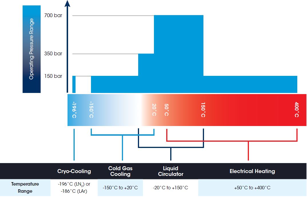
IsoSORP SA Instruments are available in configurations offering a MAXIMUM TEMPERATURE RANGE of -196°C to 400°C
Every IsoSORP instrument is equipped with a liquid circulator temperature system, providing temperature control in the range of room temperature to 150°C. For LT configurations it is available in a low temperature version providing control from -20°C to 100°C.
Cryo-Cooling is available for the Cryo configuration for isothermal testing at -196°C when using liquid nitrogen, or -186°C when using liquid argon. An optional Cold Gas Cooling System provides extended low temperature control from -150°C to a maximum of 20°C in the Cryo configuration.
Most IsoSORP instrument configurations include an electrical sample heating system, extending the temperature control range of the liquid circulators. With the electrical heating, sample temperatures from approximately 100°C to a maximum of 400°C can be controlled. For systems configured with 350 bar maximum pressure, maximum temperature is limited to 150°C when operated at pressures exceeding 150 bar.
Over twenty models of IsoSORP SA are preconfigured to meet customer application requirements. See Instrument Specifications for details.
Dosing Systems
Dosing Systems
Gas & Vapor Dosing, Blending and Pressure Control Systems
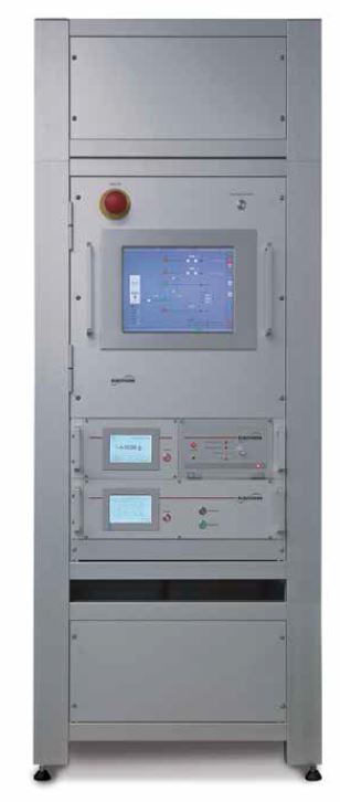 The accuracy of sorption measurements rely on accurate control of the pressure and the composition of the reaction atmosphere. The IsoSORP SA features three sophisticated gas & vapor dosing and blending systems with pressure controllers that ensure the highest data quality while providing flexibility to address the widest range of applications.
Static Pressure Controllers, for use with pure gas or vapor, fill the sample chamber with reaction atmosphere until set point is reached, after which no more gas or vapor flows. Flow Dosing and Pressure Controller systems, for use with pure gas, gas mixtures and gas & vapor mixtures, generate a continuous flow of the reaction atmosphere into the sample cell using a dynamic pressure controller in the outlet. Mix Dosing Systems are for use with gas mixtures and gas & vapor mixtures. These units allow mixing and volumetric dosing of controlled composition mixtures for selectivity measurements.
Static pressure controllers are available in unique heated versions for applications including vapors (e. g. water, hydrocarbons, solvents) and condensable fluids (e. g. CO2, NH3, butane). The heating prevents the condensation, even at high pressures. Limitations of other commercial sorption analyzers in P-controlling range are eliminated and an unmatched wide application range is realized.
The gas & vapor dosing systems are equipped with a touchscreen for display of the actual status and the pressure of the reaction atmosphere in the IsoSORP instrument. Automatic operation and data collection is controlled by the RSCS software. A list of available Gas and Vapor Dosing Systems and specifications are summarized in the table below.
| Dosing System Model | Flow / Static | Maximum Pressure[1]] | Anti-Condensation Heating |
Pure Gas, Vapor, Sub-Critical Fluid |
Mixing of Gases[2], Gases[2] + Vapor |
| 50 F-G | Flow | 50 bar | — | G, SC[3] | G |
| 50 F-G+V | 50 bar | 200°C | G, SC[3], V | G, G+V | |
| 150 F-G | 150 bar | G, SC[3] | G | ||
| 150 F-G+V | 150 bar | 200°C | G, SC[3], V | G, G+V | |
| 50 S-G+V | Static | 50 bar | 150°C | G, SC[4], V | — |
| 150 S-G | 150 bar | — | G, SC[3] | — | |
| 150 S-SC | 150 bar | 100°C | G, SC[5] | — | |
| 350 S-SC | 350 bar | 100°C | G, SC[5] | — | |
| 700 S-SC | 700 bar | 100°C | G, SC[5] | — |
[1] Vacuum specification: 0.0075 Torr possible (requires adequate vacuum pump)
[2] Including sub-critical fluids (SC) up to below specified maximum pressure limits
[3] maximum pressure for sub-critical fluids limited to ca. 40% of condensation pressure at RT
[4] maximum pressure for sub-critical fluids limited to ca. 40% of condensation pressure at 150°C
[5] maximum pressure for sub-critical fluids limited to ca. 40% of condensation pressure at 100°C
Corrosive & Toxic Gas Adsorption Measurements
Corrosive & Toxic Gas Adsorption Measurements
In many applications, toxic and/or corrosive gases are used or generated. Adsorption is often the method of choice to separate or clean mixtures containing these gases. The adsorption isotherms of all gases involved are the basis for the proper design of adsorptive cleaning processes and materials. Because the IsoSORP SA design completely isolates the reaction atmosphere from surroundings, it allows sorption measurements to be performed with corrosive and toxic gases to provide the adsorption isotherms for process and material development.
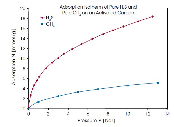
Natural and biogas can contain relatively high concentration of H2S, which is a toxic and corrosive contaminant and must be removed from the gas before using. Selective adsorption of H2S from the natural gas mixture can be used for this cleaning process – if H2S is adsorbed preferably compared to CH4, being the main component and valuable substance of natural and biogas. In the diagram below, the adsorption isotherm of pure H2S and pure CH4 on an activated carbon are compared. The measurement was performed at 25°C and over 70% of the vapor pressure range of H2S was covered. H2S adsorption is found to be about three times higher than the CH4 adsorption.
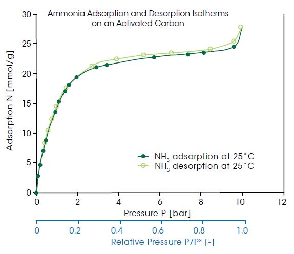
Ammonia is a toxic and corrosive substance with a high odor nuisance potential. Therefore, ammonia needs to be removed from different kinds of off gases, e. g. ventilation of farming and wastewater treatment. Additionally, adsorptive refrigeration cycles using ammonia as working fluid are considered an environmentally better alternative for providing, for instance, air conditioning. For all of these processes, the adsorption and desorption isotherm of ammonia is the basic information needed. In the diagram below, the ammonia adsorption and desorption isotherms on an activated carbon at 25°C are shown as a function of pressure. As Ammonia is a vapor at temperatures below 132.4°C, the shown isotherms are in fact vapor ad- and desorption. The relative vapor pressure range, shown in the second x-axis of the plot, covered in this measurement ranges up to 0.999.
The measurements in the below examples were performed with an IsoSORP SA (400-150, S-SC) instrument with heated pressure controller. Due to the heated pressure controller,
the sub-critical vapors H2S and NH3 can be used up to high pressures without condensation.
Toxic and Explosive Gas Adsorption Measurements
Toxic and Explosive Gas Adsorption Measurements
Often technical combustion processes do not oxidize the fuel completely. As a result, CO can be generated. Additionally, in coal and biomass gasification processes, steam reforming, and in blast furnace gas, relatively high quantities of CO are generated.
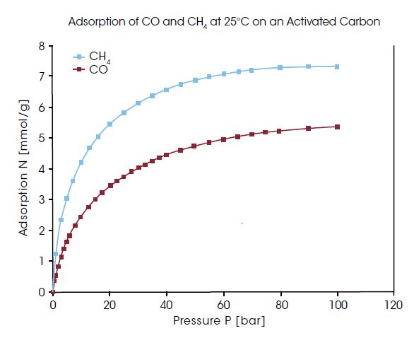
This toxic gas, which is known to poison some catalysts, has to be removed prior to further utilization in the downstream gas cleaning process. Adsorption is generally a reliable process for gas separation and cleaning. For selecting or developing the appropriate adsorbent materials, adsorption isotherms are needed. In the diagram above, the adsorption of CO and CH4 at 25°C on an activated carbon are compared up to high pressures. This adsorbent material is obviously not suited for removing CO from CH4 since CH4 is adsorbed preferably.
Measurements with permanent gases, as shown in the diagram above, can be performed with all IsoSORP SA instruments equipped with static pressure controller or flow gas dosing systems.
High Pressure Gas and Sub-Critical Fluid Sorption
High Pressure Gas and Sub-Critical Fluid Sorption
High pressure gas sorption measurements on porous, adsorbent materials provide important process and application-relevant measures for understanding the solid-gas interactions. High pressure sorption analysis not only provides quantitative mass changes and kinetic rates of adsorption and desorption, but also information about the real world, application-relevant sorption capacity, pore accessibility, and isosteric heat of adsorption. Materials commonly studied include: activated carbon, zeolites, metal hydrides, metal-organic frameworks/MOF’s and silica.
With the Rubotherm Series IsoSORP SA instruments, high pressure gas adsorption can be measured with outstanding accuracy and reproducibility. To demonstrate the reproducibility of the measurement, IsoSORP SA instruments of various configurations have been used to perform high pressure Nitrogen (N2) adsorption measurements on an internal reference material. In diagram below, the results for N2 adsorption measurements in the pressure range up to 150 bar are compared between four IsoSORP SA instruments with either static or flow configurations. The reproducibility of the measurements performed in different instruments with different configurations is excellent.
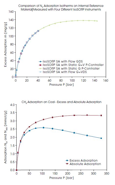
IsoSORP instruments provide the Gibbs excess adsorption data. The excess adsorption data are buoyancy / dead volume corrected, using the skeletal volume of the adsorbent material measured, with He as the reference gas. The increasing pore volume occupied by the adsorbate is neglected. As a result, excess adsorption, isotherms decline after passing through a maximum at high pressures. At high pressures, and typically high adsorption and pore occupancy, the difference between the excess adsorption and the absolute adsorption can become substantial. This is shown in the diagram on the lower right. Here, the excess adsorption of CH4 on a coal sample at 30°Cnand at pressures up to 330 bar is compared to the absolute adsorption.
The Rubotherm Series RSCS software easily performs conversion from excess adsorption to absolute adsorption based on the experimental data. The density of the adsorbate is determined from the declining part of the excess adsorption isotherm and is provided as a result of the data treatment.
High Pressure Gas and Sub-Critical Fluid Sorption
High Pressure Gas and Sub-Critical Fluid Sorption
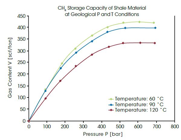
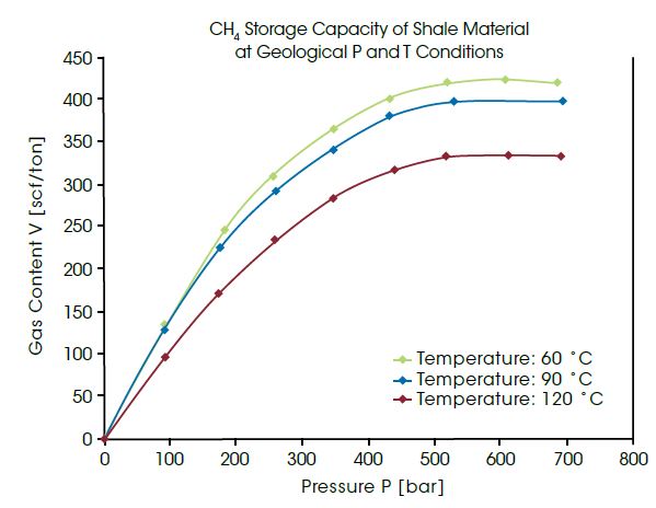
Highest pressures occur regularly in geological formations deep underground. Natural gas can be adsorbed into coal or shale formations several thousand meters deep. For utilization of these non-conventional gas reservoirs, the amount of gas in these materials must be measured under identical pressure and temperature conditions. The IsoSORP SA instruments can be used for measurements up to 700 bar and 150°C, thus being approximately the conditions at a depth of 5,000 m. The diagram below presents the measured CH4 capacity in cubic foot per ton of shale at pressures up to 700 bar and at different temperatures. The data allow conclusions to be drawn about the capacity of a geological shale gas reservoir.
Measuring high pressure sorption with fluids which are at sub-critical state at room temperature requires a completely heated instrument. Any cold spot in the wetted part of the instrument would result in the sub-critical (SC) fluid condensing and lowering the system pressure. IsoSORP SA instruments can be equipped with heated pressure controllers that ensure the temperature of all wetted parts is above the critical temperature of many technically relevant SC fluids (e. g. CO2, butane, NH3); this facilitates measurements using SC fluids at high pressures.
The lower right diagram shows the CO2 absorption in a polyether polyol at 35°C and pressures up to 80 bar*. Polyol is used to manufacture rigid polyurethane foams, and foaming is accomplished with CO2 offgassing. For process and material development, the CO2 solubility at controlled P and T needs to be known. IsoSORP SA instruments are ideally designed to generate this data.
 Non-rigid sorbent materials (e. g. polymers, ionic liquids) change their volume/density with absorbed gas. This volume change is very important for process design and data treatment. IsoSORP SA can be equipped for this purpose with a high pressure sample cell with windows allowing the volume change of the test material to be optically detected. A picture of an IsoSORP SA with high pressure sample cell with windows is provided on the right. The resulting polymer volume with absorbed CO2 is shown as green data in the diagram above*.
* Data taken from: M. R. Di Caprio, et al. : Polyether polyol/CO2 solutions: Solubility, mutual diffusivity, specific volume and interfacial tension by coupled gravimetry-Axisymmetric Drop Shape Analysis; Fluid Phase Equilibria; 425 (2016), 342-350
Vapor Adsorption
Vapor Adsorption
Many basic chemical engineering and material science applications require a fundamental understanding of vapor sorption. Some examples include drying of gases or air, cleaning of flue gases, separation of refinery gases, and wetting and drying processes of pharmaceuticals or food. For these examples and countless more, the ad-and desorption isotherms and kinetics of water and organic solvent vapors are critical for proper material formulation and/or process design.
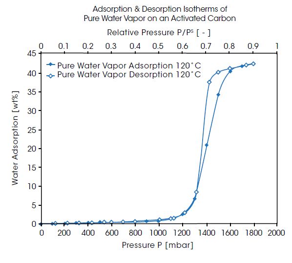
The IsoSORP SA systems configured with Gas & Vapor Dosing Systems are ideally suited for superior vapor sorption measurements. The unique design of the IsoSORP with anti-condensation heating capabilities enables measurements at very high humidity / vapor pressures, using both technically relevant humidified gas and pure vapor atmospheres. An example is shown in the right diagram for the ad- and desorption isotherms of pure water vapor (no carrier gas) at 120°C on an activated carbon. The pressure range in this measurement is up to 1.8 bar, which is about 90% saturation pressure at 120°C. The isotherms show the typical shape for a hydrophobic adsorbent material with almost no adsorption below 50% saturation. Then the adsorption increases steeply to almost 45% weight increase. The desorption isotherm shows a hysteresis loop compared to the adsorption isotherm.
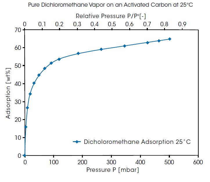
Another example is shown in the figure below for adsorption of pure dichloromethane vapor on an activated carbon at 25°C. Dichloromethane is a material widely used as a cleaning agent and solvent. This material is toxic and must not be emitted into the environment. For removal of dichloromethane and other organic solvents, adsorption on activated carbon is the standard method. The results show the organic vapor isotherm exhibits a typical Type 1 adsorption isotherm on the activated carbon with loadings up to 65 wt%.
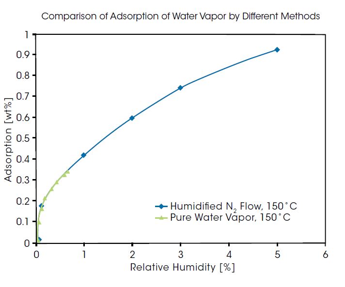
Rubotherm IsoSORP SA is available in multiple configurations for static vapor sorption measurements in pure, pressure-controlled vapor atmosphere, or in a humidified carrier gas flow. The selection of the method used for measurements depends on the specific material application, however a reliable instrument will provide equivalent results regardless of the technique. To demonstrate the superior capabilities of the IsoSORP, the figure below shows a comparison of adsorption of water vapor as pure vapor and from a N2 carrier at 150°C. It can be seen here that the IsoSORP configurations produce equivalent data regardless of the application.
- Description
-
The IsoSORP SA is an advanced gravimetric instrument featuring a patented* Magnetic Suspension Balance that enables sorption measurements under high pressure or vacuum environments.
Samples can be measured in the presence of a variety of gases or vapors over a wide temperature range covering -196°C to 400°C. A flexible selection of dosing and blending devices provide accurate control of the composition and pressure of the reaction atmosphere. Designed and built with over 20 years of experience and field-proven by hundreds of customers, the Rubotherm Series IsoSORP SA offers the widest available pressure range of all gravimetric sorption analyzers, and represents the industry standard for application-relevant analysis.
* German Patent no. 10 2009 009 204.8
- Features
-
Features and Benefits:
- Non-contact sample weighing enables hermetic separation between sample cell and balance, eliminating risk of balance damage from reaction gases, pressure or temperature inside the sample cell
- Metallically sealed sample reactor cell enables measurements in corrosive, explosive, or toxic reaction gases, from cryogenic to high temperatures, and from vacuum to high pressure.
- Unique automatic sample decoupling enables taring of balance during experiments and provides unmatched long-term baseline stability for the most accurate measurements without manual balance calibrations required by competitive devices
- Entire sample cell wetted by the reaction gases can be heated, preventing condensation of reaction gas vapors such as water vapor, CO2, ammonia etc., even at high pressures or humidity
- Gravimetric measurement of the reaction gas density in the sample cell allows automatic and accurate buoyancy correction of the gravimetric data at all pressure and temperature conditions, as well as reaction gas compositions
- The large dynamic weighing range and sample volume allows measurements with representative, large and/or heavy samples
- Specifications
-
Magnetic Suspension Balance (MSB) Pressure[1] Temperature Dosing System Type IsoSORP SA Model Resolution (μg) Mass Range (g) Max. Pressure (bar) Min (°C) Max (°C) 400-150, S-G 10 25 150 RT 400°C Static Gas
(S-G)400-150, S-G XR 1 10 150 RT 400°C 400-150, S-G Cryo 10 25 150 196°C[2] 400°C 400-150, S-G LT 10 25 150 -20 400°C 400-150, S-G XR LT 1 10 150 -20 400°C 400-50, S-G+V 10 25 50 RT 400°C Static Gas & Vapor (S-G+V) 400-50, S-G+V XR 1 10 50 RT 400°C 400-150, S-SC 10 25 150 RT 400°C Static Sub-Critical Fuids
and Gas
(S-SC)400-150, S-SC LT 10 25 150 -20 400°C 150-150, S-SC Visi 10 25 150 RT 150°C[4] 150-350, S-SC 10 25 350 RT 150°C[3] 150-350, S-SC LT 10 25 350 -20 150°C[3] 150-350, S-SC Visi 10 25 350 RT 150°C[4] 150-700, S-SC 10 25 700 RT 150°C[4] 400-50, F-G 10 25 50 RT 400°C Flow Gas
(F-G)400-50, F-G XR 1 10 50 RT 400°C 400-150, F-G 10 25 150 RT 400°C 400-150, F-G XR 1 10 150 RT 400°C 400-50, F-G+V 10 25 50 RT 400°C Flow Gas & Vapor
(F-G+V)400-50, F-G+V XR 1 10 50 RT 400°C 400-150, F-G+V 10 25 150 RT 400°C [1] Vacuum specification: 0.0075 Torr possible (requires adequate vacuum pump)
[2] Sample can be cooled to -196°C or -186°C, continuous temperature controlling range -150°C to 400°C
[3] Up to 400°C at pressures not exceeding 150 bar
[4] Not equipped with electrical heater - Technology
-
Unique Magnetic Suspension Balance Technology
Unique Magnetic Suspension Balance Technology

At the heart of every Rubotherm instrument is the patented Magnetic Suspension Balance (MSB), which weighs a sample in a closed reactor cell with an external microbalance. This is realized by means of a magnetic suspension coupling that transmits the weight force through the wall of the sample cell.
In this design, a permanent suspension magnet is attached at the top of an upper internal suspension shaft. A lower internal suspension shaft is connected to a crucible holding a sample material. Between the upper and lower suspension shafts is a load coupling mechanism. The upper and lower shafts and the sample crucible are enclosed within the sample cell.
An external electromagnet is controlled to attract the internal permanent magnet. This raises the internal suspension magnet and engages the load coupling and, as a result, raises the sample crucible. The electromagnet control continues to apply attractive force until the system reaches a constant measuring point height.
The weight of the sample in the cell is determined by the external microbalance, to which the electromagnet is connected, with high resolution and accuracy.
Automatic Sample Decoupling Feature (ASD)
Automatic Sample Decoupling Feature (ASD)
At the start of any gravimetric experiment, the balance is automatically tared and calibrated to establish a “zero-point” for the weight measurement. This zero-point is the value used for all subsequent measurements. However, as experiment time frames can vary from hours to weeks, the ability to accurately measure small weight changes over extended times can be diminished by drift in the zero-point. Drift is typically due to external factors such as fluctuations in laboratory temperature and air pressure or humidity.
Attempts to improve signal accuracy have traditionally been to conduct empty crucible baseline runs and subtracting them from the sample run. This method is not ideal as it doubles experiment times, and is inherently flawed as no two experiments are ever exactly the same. Only TA’s IsoSORP SA, with patented MSB technology, provides the unique Automatic Sample Decoupling (ASD) feature for real-time drift corrections, increasing weight accuracy to previously unattainable levels, especially for long-term measurements.
How ASD Works:

As shown in the figure above, the MSB design includes a shaft load coupling. When the electromagnet is energized, it attracts the permanent magnet that is connected to the upper shaft. The upper shaft lifts upward, engages the coupling, and raises the crucible to the measuring point to make the weight measurement. At any time during the experiment, the permanent suspension magnet can be moved downward to decouple from the sample crucible.
During this downward movement, the shaft load coupling is placed at rest on a support. The suspension magnet remains in a free-floating state, transferring only its weight to the balance. By moving to this new zero-point position corresponding to an unloaded balance, taring and calibrating are possible during measurements, even under process conditions (pressure, temperature) in the sample cell. This unique automatic software-controlled calibration of the balance, during measurements, is available ONLY on TA Instruments’ commercial gravimetric analyzer.
Dual-Sample Weight and Gas Phase Density Measurements
Dual-Sample Weight and Gas Phase Density Measurements
The IsoSORP can be configured with a second load coupling and sample position, enabling the weight measurement of two samples during a single experiment. This function can be used for comparative measurements of two samples (e. g. comparison of reactive and reference samples), or for determination of both sorption and density of the gaseous atmosphere in the reactor.

The second coupling and sample position creates a total of three vertical positions to which the MSB is controlled. These include the Zero Point, or Tare position, Measuring Point 1, and Measuring Point 2. This capability is demonstrated through a series of schematic diagrams in the figure above follows:
- Zero Point Position: Only the permanent magnet is suspended in order to tare and/or calibrate the microbalance.
- Measuring Point 1: The permanent magnet is raised, engaging the first coupling where the weight of the first reactive sample (adsorbent, catalyst, organic materials, etc.) is determined for sorption measurement 1.
- Measuring Point 2: With the first coupling engaged, the permanent magnet is raised further to engage the second coupling, lifting and weighing the combined mass of both samples. By subtracting the weight measured in Measuring Point 1 from the combined weight, the weight of the second sample is determined for sorption measurement 2. In the case of determining the density of the fluid phase in the reactor, an inert sinker with known volume serves as the second sample. Using the Archimedes principle, the density of the gas phase in the reactor is precisely determined from the buoyancy force acting on the sinker.
Automatic Buoyancy Correction for Unrivaled True Mass Accuracy
Automatic Buoyancy Correction for Unrivaled True Mass Accuracy

In sorption measurements, a sample is exposed to a reaction gas at controlled temperature and pressure. Usually the pressure is incremented in a stepwise fashion, and the sample mass changes due to adsorption or absorption of the gas in/on the sample are measured. Along with sample mass, gas phase density changes with pressure and/or temperature, resulting in a change in buoyancy effect acting on the sample. The buoyancy effect is the mass of the reaction gas atmosphere which is displaced by the sample, resulting in the ”apparent” loss of sample mass or an “apparent sample mass” measurement as observed by the balance. The buoyancy effect must be corrected to obtain the “true sample mass.”
Any balance can only measure the difference between the true sample mass and the buoyancy effect acting on the sample, or the so-called apparent mass. To correct sample mass for the buoyancy effect, the mass of the displaced gas, (mG) , must be added to the apparent sample mass weighed by the balance, (Δm), (Equation 1). To accurately determine the mass of the displaced gas, both the volume of the sample, (V), and density of the gas, (ρG), must be known (Equation 2).

Unlike conventional sorption analyzers which rely on pressure and temperature data to calculate ρG from equations of state, the IsoSORP conducts a direct gravimetric measurement. The unique design incorporates a second weighing position where an inert “sinker” of known mass and volume is placed. A simple weight measurement of the “sinker” provides a direct in-situ determination of the actual ρG . This is much more accurate than the calculation method and, as it is a direct measurement of the density, it provides correct results even if the reaction gas is not a pure fluid.
In addition, the IsoSORP automatically determines sample volume accurately through a buoyancy measurement using He as a reaction gas. Because the IsoSORP is the only instrument to make direct, highly accurate measurements of both ρG and V, the mass of the displaced gas is also directly determined, providing unrivaled accuracy in the measurement of the sample’s true mass.
Sample Temperature Control
Sample Temperature Control

IsoSORP SA Instruments are available in configurations offering a MAXIMUM TEMPERATURE RANGE of -196°C to 400°C
Every IsoSORP instrument is equipped with a liquid circulator temperature system, providing temperature control in the range of room temperature to 150°C. For LT configurations it is available in a low temperature version providing control from -20°C to 100°C.
Cryo-Cooling is available for the Cryo configuration for isothermal testing at -196°C when using liquid nitrogen, or -186°C when using liquid argon. An optional Cold Gas Cooling System provides extended low temperature control from -150°C to a maximum of 20°C in the Cryo configuration.
Most IsoSORP instrument configurations include an electrical sample heating system, extending the temperature control range of the liquid circulators. With the electrical heating, sample temperatures from approximately 100°C to a maximum of 400°C can be controlled. For systems configured with 350 bar maximum pressure, maximum temperature is limited to 150°C when operated at pressures exceeding 150 bar.
Over twenty models of IsoSORP SA are preconfigured to meet customer application requirements. See Instrument Specifications for details.
Dosing Systems
Dosing Systems
Gas & Vapor Dosing, Blending and Pressure Control Systems
 The accuracy of sorption measurements rely on accurate control of the pressure and the composition of the reaction atmosphere. The IsoSORP SA features three sophisticated gas & vapor dosing and blending systems with pressure controllers that ensure the highest data quality while providing flexibility to address the widest range of applications.
Static Pressure Controllers, for use with pure gas or vapor, fill the sample chamber with reaction atmosphere until set point is reached, after which no more gas or vapor flows. Flow Dosing and Pressure Controller systems, for use with pure gas, gas mixtures and gas & vapor mixtures, generate a continuous flow of the reaction atmosphere into the sample cell using a dynamic pressure controller in the outlet. Mix Dosing Systems are for use with gas mixtures and gas & vapor mixtures. These units allow mixing and volumetric dosing of controlled composition mixtures for selectivity measurements.
Static pressure controllers are available in unique heated versions for applications including vapors (e. g. water, hydrocarbons, solvents) and condensable fluids (e. g. CO2, NH3, butane). The heating prevents the condensation, even at high pressures. Limitations of other commercial sorption analyzers in P-controlling range are eliminated and an unmatched wide application range is realized.
The gas & vapor dosing systems are equipped with a touchscreen for display of the actual status and the pressure of the reaction atmosphere in the IsoSORP instrument. Automatic operation and data collection is controlled by the RSCS software. A list of available Gas and Vapor Dosing Systems and specifications are summarized in the table below.
Dosing System Model Flow / Static Maximum Pressure[1]] Anti-Condensation
HeatingPure Gas, Vapor,
Sub-Critical FluidMixing of
Gases[2],
Gases[2] + Vapor50 F-G Flow 50 bar — G, SC[3] G 50 F-G+V 50 bar 200°C G, SC[3], V G, G+V 150 F-G 150 bar G, SC[3] G 150 F-G+V 150 bar 200°C G, SC[3], V G, G+V 50 S-G+V Static 50 bar 150°C G, SC[4], V — 150 S-G 150 bar — G, SC[3] — 150 S-SC 150 bar 100°C G, SC[5] — 350 S-SC 350 bar 100°C G, SC[5] — 700 S-SC 700 bar 100°C G, SC[5] — [1] Vacuum specification: 0.0075 Torr possible (requires adequate vacuum pump)
[2] Including sub-critical fluids (SC) up to below specified maximum pressure limits
[3] maximum pressure for sub-critical fluids limited to ca. 40% of condensation pressure at RT
[4] maximum pressure for sub-critical fluids limited to ca. 40% of condensation pressure at 150°C
[5] maximum pressure for sub-critical fluids limited to ca. 40% of condensation pressure at 100°C - Applications
-
Corrosive & Toxic Gas Adsorption Measurements
Corrosive & Toxic Gas Adsorption Measurements
In many applications, toxic and/or corrosive gases are used or generated. Adsorption is often the method of choice to separate or clean mixtures containing these gases. The adsorption isotherms of all gases involved are the basis for the proper design of adsorptive cleaning processes and materials. Because the IsoSORP SA design completely isolates the reaction atmosphere from surroundings, it allows sorption measurements to be performed with corrosive and toxic gases to provide the adsorption isotherms for process and material development.
Natural and biogas can contain relatively high concentration of H2S, which is a toxic and corrosive contaminant and must be removed from the gas before using. Selective adsorption of H2S from the natural gas mixture can be used for this cleaning process – if H2S is adsorbed preferably compared to CH4, being the main component and valuable substance of natural and biogas. In the diagram below, the adsorption isotherm of pure H2S and pure CH4 on an activated carbon are compared. The measurement was performed at 25°C and over 70% of the vapor pressure range of H2S was covered. H2S adsorption is found to be about three times higher than the CH4 adsorption.

Ammonia is a toxic and corrosive substance with a high odor nuisance potential. Therefore, ammonia needs to be removed from different kinds of off gases, e. g. ventilation of farming and wastewater treatment. Additionally, adsorptive refrigeration cycles using ammonia as working fluid are considered an environmentally better alternative for providing, for instance, air conditioning. For all of these processes, the adsorption and desorption isotherm of ammonia is the basic information needed. In the diagram below, the ammonia adsorption and desorption isotherms on an activated carbon at 25°C are shown as a function of pressure. As Ammonia is a vapor at temperatures below 132.4°C, the shown isotherms are in fact vapor ad- and desorption. The relative vapor pressure range, shown in the second x-axis of the plot, covered in this measurement ranges up to 0.999.

The measurements in the below examples were performed with an IsoSORP SA (400-150, S-SC) instrument with heated pressure controller. Due to the heated pressure controller,
the sub-critical vapors H2S and NH3 can be used up to high pressures without condensation.
Toxic and Explosive Gas Adsorption Measurements
Toxic and Explosive Gas Adsorption Measurements

Often technical combustion processes do not oxidize the fuel completely. As a result, CO can be generated. Additionally, in coal and biomass gasification processes, steam reforming, and in blast furnace gas, relatively high quantities of CO are generated.
This toxic gas, which is known to poison some catalysts, has to be removed prior to further utilization in the downstream gas cleaning process. Adsorption is generally a reliable process for gas separation and cleaning. For selecting or developing the appropriate adsorbent materials, adsorption isotherms are needed. In the diagram above, the adsorption of CO and CH4 at 25°C on an activated carbon are compared up to high pressures. This adsorbent material is obviously not suited for removing CO from CH4 since CH4 is adsorbed preferably.Measurements with permanent gases, as shown in the diagram above, can be performed with all IsoSORP SA instruments equipped with static pressure controller or flow gas dosing systems.
High Pressure Gas and Sub-Critical Fluid Sorption
High Pressure Gas and Sub-Critical Fluid Sorption
High pressure gas sorption measurements on porous, adsorbent materials provide important process and application-relevant measures for understanding the solid-gas interactions. High pressure sorption analysis not only provides quantitative mass changes and kinetic rates of adsorption and desorption, but also information about the real world, application-relevant sorption capacity, pore accessibility, and isosteric heat of adsorption. Materials commonly studied include: activated carbon, zeolites, metal hydrides, metal-organic frameworks/MOF’s and silica.
With the Rubotherm Series IsoSORP SA instruments, high pressure gas adsorption can be measured with outstanding accuracy and reproducibility. To demonstrate the reproducibility of the measurement, IsoSORP SA instruments of various configurations have been used to perform high pressure Nitrogen (N2) adsorption measurements on an internal reference material. In diagram below, the results for N2 adsorption measurements in the pressure range up to 150 bar are compared between four IsoSORP SA instruments with either static or flow configurations. The reproducibility of the measurements performed in different instruments with different configurations is excellent.

IsoSORP instruments provide the Gibbs excess adsorption data. The excess adsorption data are buoyancy / dead volume corrected, using the skeletal volume of the adsorbent material measured, with He as the reference gas. The increasing pore volume occupied by the adsorbate is neglected. As a result, excess adsorption, isotherms decline after passing through a maximum at high pressures. At high pressures, and typically high adsorption and pore occupancy, the difference between the excess adsorption and the absolute adsorption can become substantial. This is shown in the diagram on the lower right. Here, the excess adsorption of CH4 on a coal sample at 30°Cnand at pressures up to 330 bar is compared to the absolute adsorption.
The Rubotherm Series RSCS software easily performs conversion from excess adsorption to absolute adsorption based on the experimental data. The density of the adsorbate is determined from the declining part of the excess adsorption isotherm and is provided as a result of the data treatment.
High Pressure Gas and Sub-Critical Fluid Sorption
High Pressure Gas and Sub-Critical Fluid Sorption
Highest pressures occur regularly in geological formations deep underground. Natural gas can be adsorbed into coal or shale formations several thousand meters deep. For utilization of these non-conventional gas reservoirs, the amount of gas in these materials must be measured under identical pressure and temperature conditions. The IsoSORP SA instruments can be used for measurements up to 700 bar and 150°C, thus being approximately the conditions at a depth of 5,000 m. The diagram below presents the measured CH4 capacity in cubic foot per ton of shale at pressures up to 700 bar and at different temperatures. The data allow conclusions to be drawn about the capacity of a geological shale gas reservoir.

Measuring high pressure sorption with fluids which are at sub-critical state at room temperature requires a completely heated instrument. Any cold spot in the wetted part of the instrument would result in the sub-critical (SC) fluid condensing and lowering the system pressure. IsoSORP SA instruments can be equipped with heated pressure controllers that ensure the temperature of all wetted parts is above the critical temperature of many technically relevant SC fluids (e. g. CO2, butane, NH3); this facilitates measurements using SC fluids at high pressures.
The lower right diagram shows the CO2 absorption in a polyether polyol at 35°C and pressures up to 80 bar*. Polyol is used to manufacture rigid polyurethane foams, and foaming is accomplished with CO2 offgassing. For process and material development, the CO2 solubility at controlled P and T needs to be known. IsoSORP SA instruments are ideally designed to generate this data.

 Non-rigid sorbent materials (e. g. polymers, ionic liquids) change their volume/density with absorbed gas. This volume change is very important for process design and data treatment. IsoSORP SA can be equipped for this purpose with a high pressure sample cell with windows allowing the volume change of the test material to be optically detected. A picture of an IsoSORP SA with high pressure sample cell with windows is provided on the right. The resulting polymer volume with absorbed CO2 is shown as green data in the diagram above*.
* Data taken from: M. R. Di Caprio, et al. : Polyether polyol/CO2 solutions: Solubility, mutual diffusivity, specific volume and interfacial tension by coupled gravimetry-Axisymmetric Drop Shape Analysis; Fluid Phase Equilibria; 425 (2016), 342-350
Vapor Adsorption
Vapor Adsorption
Many basic chemical engineering and material science applications require a fundamental understanding of vapor sorption. Some examples include drying of gases or air, cleaning of flue gases, separation of refinery gases, and wetting and drying processes of pharmaceuticals or food. For these examples and countless more, the ad-and desorption isotherms and kinetics of water and organic solvent vapors are critical for proper material formulation and/or process design.
The IsoSORP SA systems configured with Gas & Vapor Dosing Systems are ideally suited for superior vapor sorption measurements. The unique design of the IsoSORP with anti-condensation heating capabilities enables measurements at very high humidity / vapor pressures, using both technically relevant humidified gas and pure vapor atmospheres. An example is shown in the right diagram for the ad- and desorption isotherms of pure water vapor (no carrier gas) at 120°C on an activated carbon. The pressure range in this measurement is up to 1.8 bar, which is about 90% saturation pressure at 120°C. The isotherms show the typical shape for a hydrophobic adsorbent material with almost no adsorption below 50% saturation. Then the adsorption increases steeply to almost 45% weight increase. The desorption isotherm shows a hysteresis loop compared to the adsorption isotherm.

Another example is shown in the figure below for adsorption of pure dichloromethane vapor on an activated carbon at 25°C. Dichloromethane is a material widely used as a cleaning agent and solvent. This material is toxic and must not be emitted into the environment. For removal of dichloromethane and other organic solvents, adsorption on activated carbon is the standard method. The results show the organic vapor isotherm exhibits a typical Type 1 adsorption isotherm on the activated carbon with loadings up to 65 wt%.

Rubotherm IsoSORP SA is available in multiple configurations for static vapor sorption measurements in pure, pressure-controlled vapor atmosphere, or in a humidified carrier gas flow. The selection of the method used for measurements depends on the specific material application, however a reliable instrument will provide equivalent results regardless of the technique. To demonstrate the superior capabilities of the IsoSORP, the figure below shows a comparison of adsorption of water vapor as pure vapor and from a N2 carrier at 150°C. It can be seen here that the IsoSORP configurations produce equivalent data regardless of the application.


