Keywords: Thermal analysis, TGA, thermogravimetric analysis, engine oil, lubricant, modulated thermal analysis, modulated TGA, MTGA, oil stability, Arrhenius analysis, numerical analysis, curve-fitting
TA452
Abstract
Thermogravimetric analysis (TGA) is commonly used to assess the thermal stability of materials including lubricant oils by measuring mass loss as a function of temperature or time. Modulated thermogravimetric analysis (MTGA) superimposes a sinusoidal heating rate on the linear heating rate which allows calculation of the activation energy (ΔE) and pre-exponential (Z) in a single experiment. The activation energy is related to the stability of the sample and can be used to estimate time to failure using established numerical methods.
In this work, five commercially available engine oils were compared. We identified stability differences between the oils, and as expected some were very similar. We also estimated the time to failure at 20% mass loss (1 quart low in many engines) at engine operating temperatures including a temperature that would represent extreme overheating. Additionally, we gained insight into differences in decomposition mechanisms by numerical treatment of rate of mass loss data as well as determining the activation energy as a function of conversion.
Introduction
Modulated differential scanning calorimetry (MDSC) was introduced in 1992 by Mike Reading [1] in which a sine wave temperature oscillatory forcing function produces a corresponding heat flow response in a differential scanning calorimeter (DSC) experiment. The heating rate is schematically represented in Figure 1.
For the DSC experiment, the overall heat flow rate dQ/dt can be expressed as:

Where Cp is the specific heat capacity, (dT/dt) is the heating rate, and f(T,t) is a summation of heat flows dependent on time and temperature – typically Arrhenius functions. Deconvolution of the oscillatory heating rate and resultant heat flow leads to separation of the product Cp(dT/dt) which is described as the heat capacity (heating rate dependent) component from f(T,t) which is described as the kinetic component [3] [4].
The modulated experiment can also be applied to thermogravimetry using a sinusoidal temperature forcing function resulting in an oscillatory rate of mass loss and described by the following analogous equation:

Where dw/dt is the rate of mass loss. As thermal decomposition is purely kinetic, any heating rate dependent contribution is zero and the rate of mass loss (dw/dt) which we express in more general terms as (dα/dt) is directly proportional to only the kinetic component and written using the familiar kinetic equation:

![TA452_Fig.1 Figure 1. Linear and Sinusoidal Heating in MDSC Experiment [2]](https://www.tainstruments.com/wp-content/uploads/TA452_Fig.1.png)
Where dα/dt is the rate of the chemical reaction, in this case mass loss, α is the extent of the reaction and f(α) is the reaction model. The temperature dependent component F(T) is described by the Arrhenius relation [3].
Estimation of sample stability is often done by a non-isothermal experiment described in ASTM E1641 [5] based on the method of by Ozawa, Flynn, and Wall. The sample is run at several heating rates and the natural log of the heating rates is plotted as a function of the reciprocal temperature obtained at some arbitrary level of conversion typically 5% or less. The pre-exponential and activation energy (ΔE) are calculated from the Arrhenius relation using an iterative integral process. It is assumed that f(α) = (1-α)n where n = 1. The method is also summarized in applications note TA125 [6] available here.
The development of the thermobalance in the early twentieth century led to the first non-isothermal kinetics analysis. In 1925, investigating of the effect of temperature on cellulosic insulating materials Kujirai and Akahira found that a series of isothermal mass loss experiments resulted in a plot of the log of the time to reach a degree of conversion vs 1/T (absolute temperature) resulted in a series of parallel isogravimetrics. The authors also proposed that the independence of f(α) and T could be tested by cycling abruptly between two temperatures T1 and T2 and comparing with the isothermal [7] [8].
One complication of running samples at different heating rates is the variation in experimental conditions may result in physical or chemical changes at the same fractional mass loss affecting not only the f(α) term but possibly the F(T) term [9]. One example is a polymer that may crystallize upon heating. At a slower heating rate, more crystallization may occur resulting in the sample being more thermally stable potentially giving a higher value of ΔE.
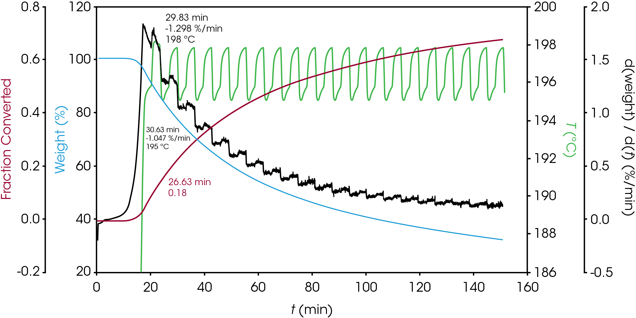
In the late 1960’s Flynn introduced the factor jump method in which the temperature T1 is held for a time period t1 and then held at T2 so that distinct rates of mass loss can be observed, but the extent of conversion is approximately constant. This results in minimal physical change to the specimen in the narrow temperature interval. The factor jump method is shown schematically in Figure 2 and has been standardized in ASTM E2958 [10]. An example of the factor jump method applied to one of the oil samples is shown in Figure 3. The forcing function is a ramp at 10 °C / min to the upper temperature, hold for 3 minutes, followed by ramp at 10 °C / min to the lower temperature. The response is observed in the rate of mass loss (dα/dt). Using Equation 5 an activation energy of 131.3 kJ/mol was calculated at α = 0.22.
![TA452_Fig.2 Figure 2. Schematic of Factor Jump Method. Rate of mass loss vs time. T1→ T2 at t1, T2→ T1 at t2 [9]](https://www.tainstruments.com/wp-content/uploads/TA452_Fig.2.png)
ASTM E2958 designates the upper temperature as TP and the lower temperature as TV. Equation 3 can be written for each measured rate of mass loss (dα/dt)P and (dα/dt)V. If the temperature interval is sufficiently small, αP ≈ αV, the ratio of the mass loss rates at TP and TV can be written using Equation 4:

The activation energy can be solved using Equation 5:

The pre-exponential Z is calculated using Equation 6:

T = (TP + TV) / 2
(7)
In 1969, Flynn [8] also proposed that a sinusoidal forcing function could be used to obtain TP and TV:
TP = T0 + TA sin(ωt)
(8)
TV = T0 – TA sin(ωt)
(9)
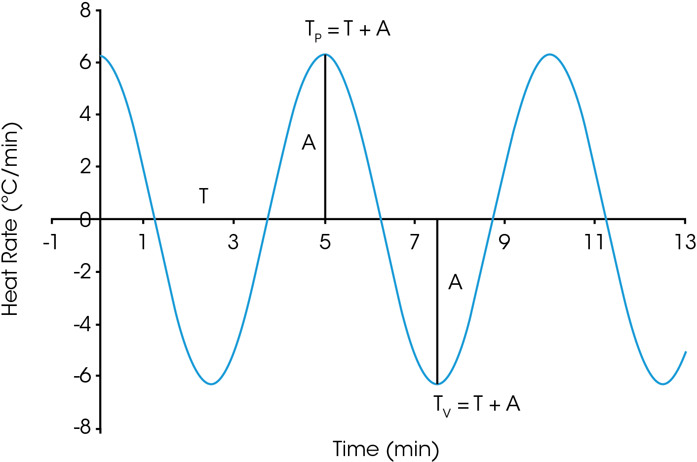
Where ω = 2π / period(s) and is the angular velocity. Note that the period is a user entered parameter in the mTGA experiment. Any modulated thermal experiment is defined by the average temperature, the amplitude, and the period. The values of TP and TV can be replaced by T+A and T-A respectively. The instantaneous heating rate is schematically represented in Figure 4.
Simplifying Equation 5, the activation energy is:

The pre-exponential Z can also be calculated:

Where:
(da/dt) = average rate of mass loss in the period T = average temperature in the period
Any periodic function can be used as long as the period is long enough to maintain equilibrium between the rate of mass loss and the oscillatory temperature forcing function [3].
Background
Engine oils are mixtures of base oil, and a complex array of additives including antioxidants, dispersants, friction modifiers, detergents, anti-wear additives, anti-foam additives, corrosion inhibitors, viscosity modifiers, and pour point depressants. The base oil is about 70-90% of the formulation with the additives making up the remainder. Engine oils are designed to protect the engine from wear, lubricate moving parts, improve efficiency, cool the engine, and prevent the accumulation of dirt and sludge by removing and suspending it until the next oil change. Ideally, all these functions happen in a wide operating temperature range. In this work, modulated TGA is used to gain further insight into the stability and decomposition mechanisms of engine oils as well provide an additional tool in designing engine oil formulations.
Experimental
For this work we chose five commercial engine lubricants designated as A, B, C, D, and E. Oxidative stability is one of the criteria for predicting the lifetime of an engine oil. The TGA experiment measures mass loss which can occur by vaporization, sublimation, or desorption. In addition to the TGA data, we will also compare activation energy at levels of conversion of 0.5, 1, 2, and 10 %. The experiment was run in air using four repetitions in platinum crucibles. The TRIOS software allows easy averaging of the repetitions which reduces the data analysis time.
Table 1. Modulated TGA Experimental Parameters
| Instrument | TA Instruments Discovery 5500 |
|---|---|
| Sample Mass | 5 mg nominal |
| Crucible | Platinum |
| Purge gas | Air at 25 mL / min |
| Ramp Rate | 1 °C / min from ambient to 500 °C, 4 repetitions of each sample |
| Modulation period | 300 s |
| Amplitude | ± 5° C |
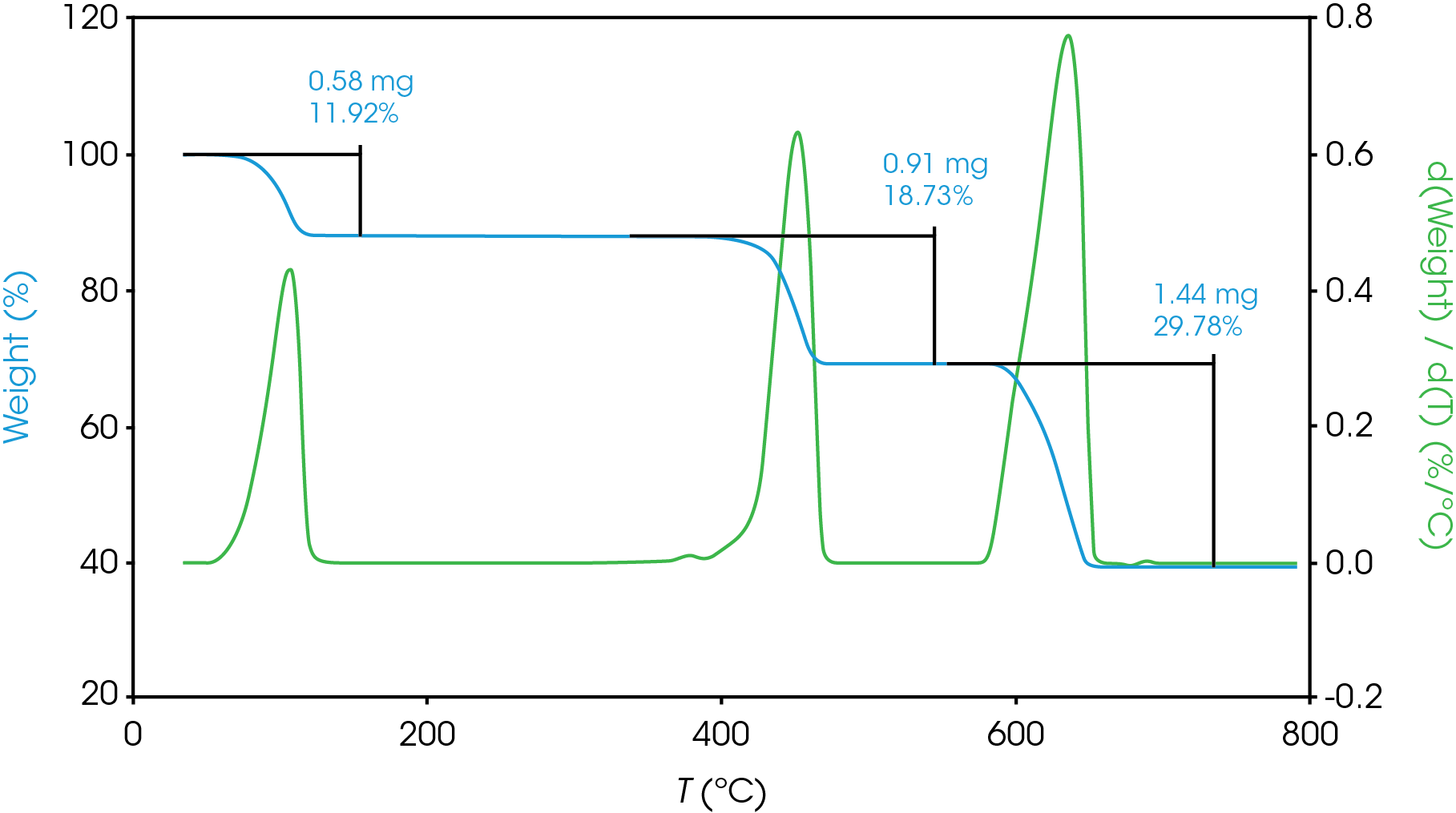
Data reduction for completely single mass loss or completely resolved mass losses is simple. Figure 5 shows three resolved mass losses for calcium oxalate, a compound often used to check performance of a TGA. Choosing limits for these completely resolved mass losses is simple, and plotting the derivative curve is commonly used to aid this process.
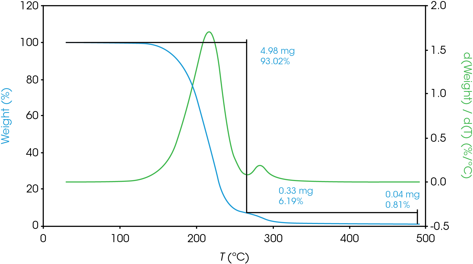
For partially resolved mass losses, choosing the local minimum of the derivative curve is a reasonable method for estimating overlapping mass losses. Figure 6 shows an example of this with the derivative curve shown in blue, mass loss shown in green.
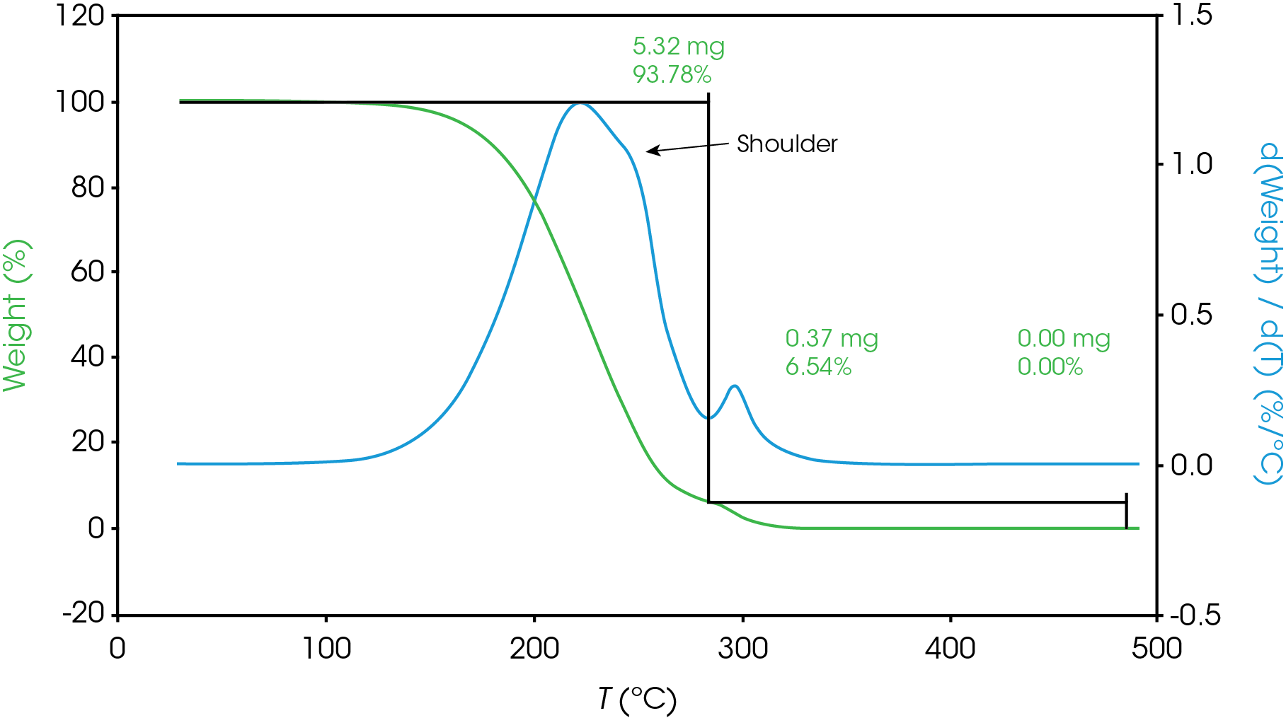
For mass losses showing poor resolution, the analysis is more complex. Figure 7 shows a partially resolved mass loss as well as a shoulder which is difficult to analyze using the local derivative minima method.
For this situation, we will use a numerical method to fit the derivative curve to estimate the mass fraction contributions to the total mass loss event. In a previous work [11] we demonstrated how this method may be used in the TGA experiment. We will also use a numerical approach to estimate the partially resolved mass losses described in Figure 6. The mathematical model we used to fit our data was the Pearson IV, but others can be used [11].
Results and Discussion
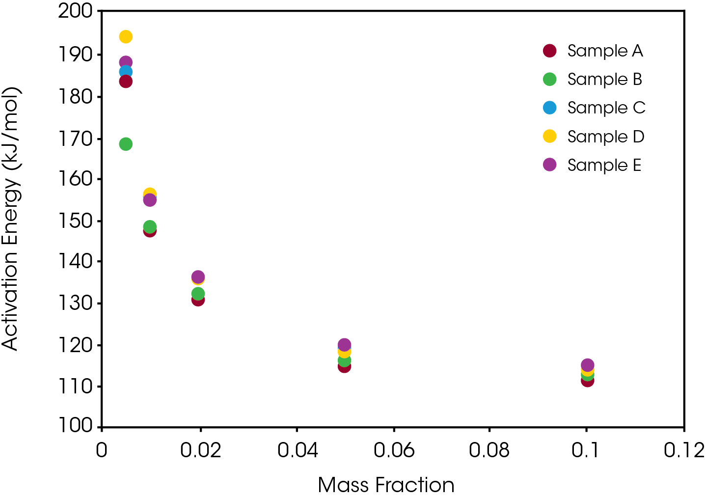
Table 2 and Figure 8 summarize the activation energies obtained at conversion (α) of 0.5, 1.0, 2.0, 5.0 and 10.0%, Table 3 summarizes the relative standard deviations of the average of four runs of the activation energy.
Table 2. Activation Energies of Lubricant Oils at Levels of Conversion (Average of Four Runs)
| α (%) | A | B | C | D | E |
|---|---|---|---|---|---|
| ΔE | kJ/mol | ||||
| 0.5 | 181.3 | 166.2 | 182.0 | 190.1 | 182.4 |
| 1.0 | 147.4 | 145.8 | 154.0 | 155.7 | 153.9 |
| 2.0 | 130.5 | 132.4 | 136.8 | 136.2 | 135.2 |
| 5.0 | 115.9 | 116.4 | 120.0 | 118.1 | 119.9 |
| 10.0 | 110.9 | 12.8 | 113.7 | 113.5 | 115.4 |
Table 3. Relative Standard Deviations of Activation Energy (Average of Four Runs)
| α (%) | A | B | C | D | E |
|---|---|---|---|---|---|
| 0.5 | 11.4% | 6.6% | 10.9% | 9.0% | 7.1% |
| 1.0 | 2.7% | 4.2% | 2.8% | 5.8% | 1.3% |
| 2.0 | 1.2% | 2.1% | 1.8% | 4.5% | 3.2% |
| 5.0 | 1.1% | 1.6% | 1.3% | 1.9% | 0.8% |
| 10.0 | 0.9% | 1.4% | 0.9% | 1.0% | 0.9% |
There is some differentiation between the samples in the lower levels of conversion, but not enough to draw significant conclusions relating relative stability from the activation energy alone. The samples converge at about 5% mass loss.
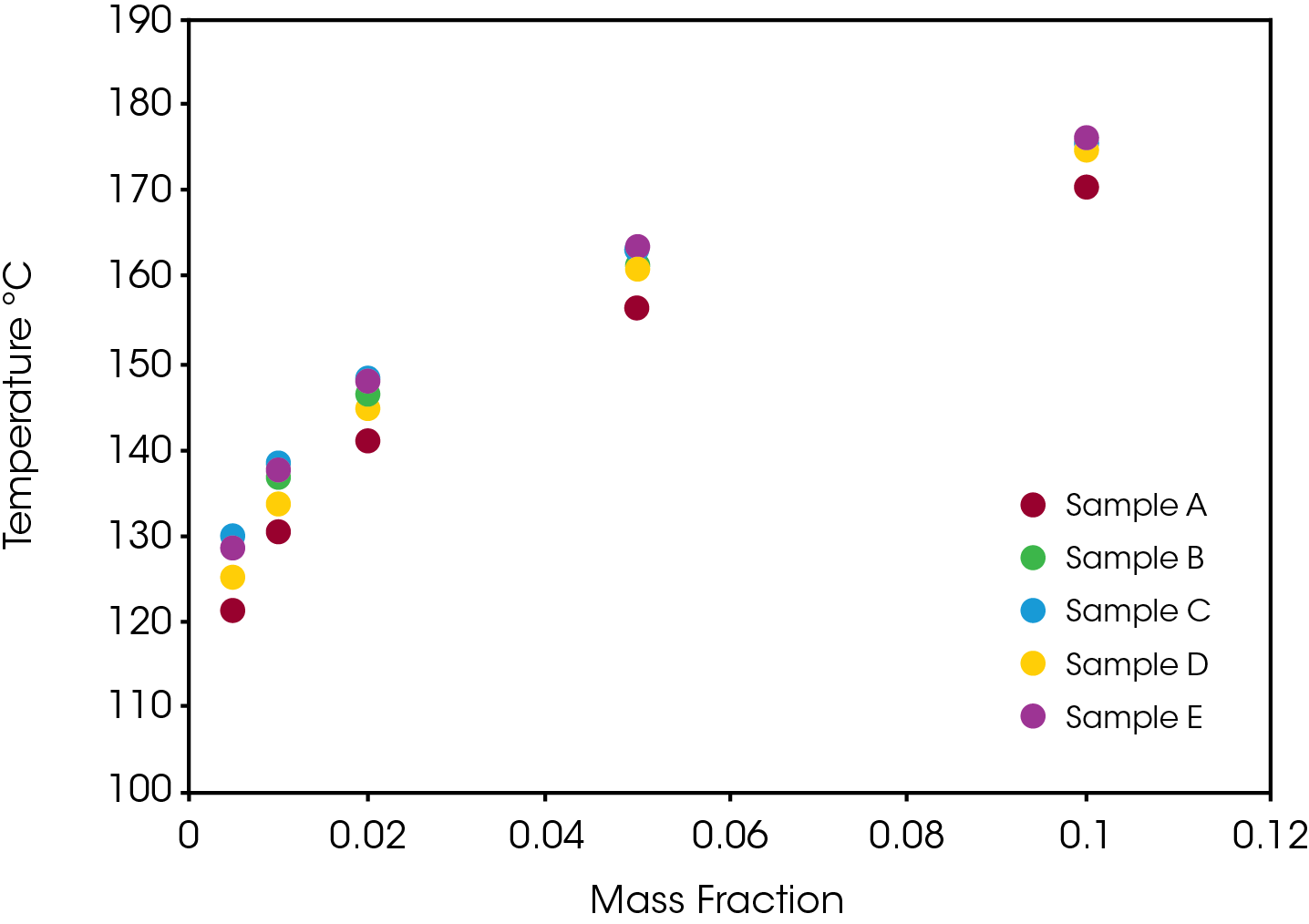
Another perspective on stability is shown in Figure 9 which compares the temperature that each of the samples reaches different levels of conversion. Sample A consistently shows the least stability relative to the other samples which are somewhat differentiated at lower conversion levels and converge at higher conversions.
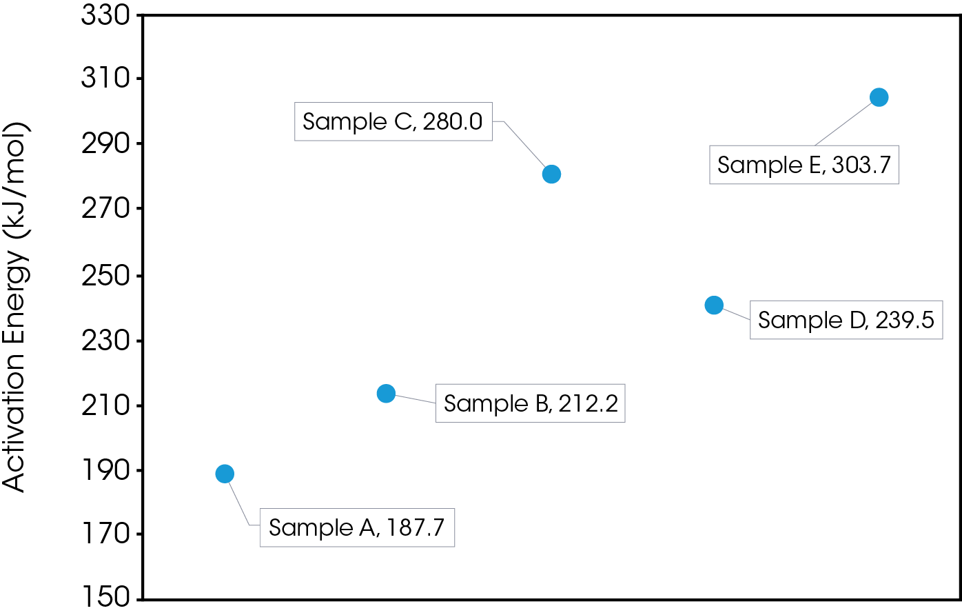
The activation energy was also obtained for the samples at 120 °C chosen to simulate a severe temperature condition as well as minimize the number of competing chemical reactions occurring during decomposition. In this case we do observe significant differences in the activation energies with sample A having the lowest activation energy and sample E having the highest. These results are shown in Figure 10.
The lifetime of the engine oils was also estimated using the protocols established in ASTM E1641 [5] and E1877 [12]. Figure 11 shows a comparison of estimated lifetimes to 20% conversion which represents an engine with five-quart capacity being a quart low. Results are also summarized in Table 4. The stability results show samples D and E are most stable and approximately equal, sample B more stable than sample C, and sample A least stable. Typically, a mileage interval is used in determining when to change an engine oil. Each of the oils shows good stability in the ‘normal’ operating temperature range between 90 – 100 °C, but significant differences are evident in the extreme temperature ranges. Engine operating time may be a better measure (as used in aircraft maintenance) as it would better account for ‘stop and go’ driving. Non-operating time may also be important as accumulating moisture could contaminate the oil.
Table 4. Time to Fail Comparison of Engine Oils (20%) at 4 Temperatures
| T(ºC) | A | B | C | D | E |
|---|---|---|---|---|---|
| Time (hours) | |||||
| 90 | 514.0 | 682.3 | 635.5 | 794.5 | 803.0 |
| 100 | 192.8 | 256.5 | 273.8 | 298.3 | 297.5 |
| 110 | 76.1 | 101.5 | 93.7 | 117.8 | 116.1 |
| 120 | 31.5 | 42.2 | 38.7 | 48.8 | 47.6 |
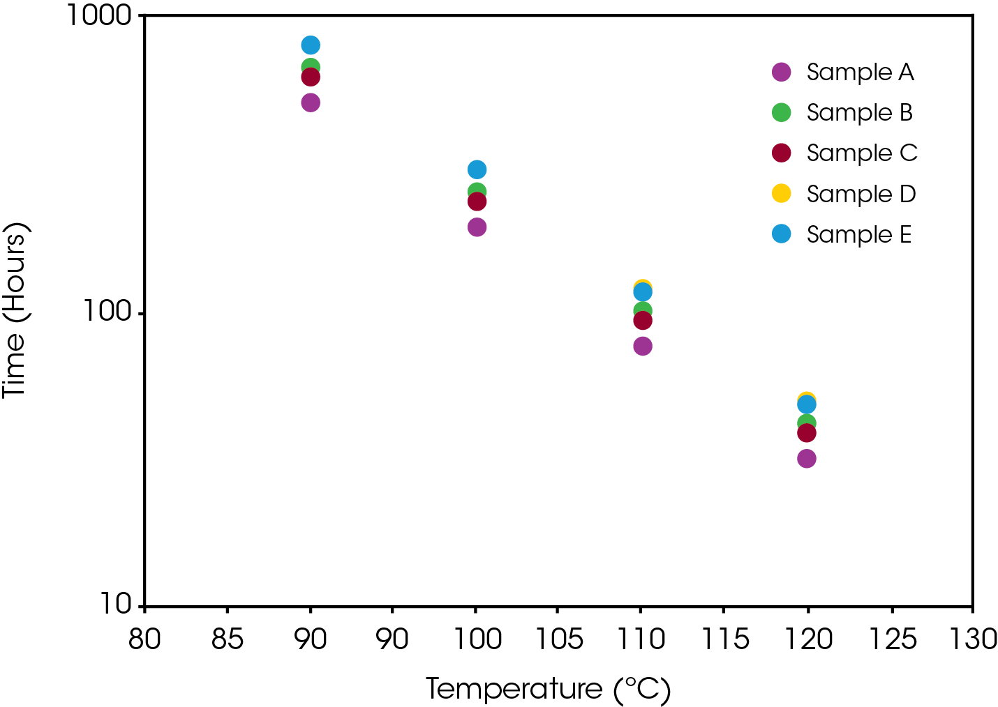
For comparing the mass loss data, a type IV base oil was obtained as a reference since it does not contain a viscosity modifier.
Figure 12 shows a comparison of the TGA data for each of the oil samples and Table 5 enumerates and describes the mass loss events. The decomposition mechanisms appear to vary as evidenced by the presence of a shoulder in the derivative curve of the larger (first) mass loss in samples A, B, D, and E. Sample C and the base oil do not show this shoulder to an appreciable degree.
Table 5. Sample and resolution type
| Sample | Number of mass losses | Comment |
|---|---|---|
| Base | 1 | Single mass loss |
| A | 2 | Partially resolved, shoulder |
| B | 3 | Partial resolution, shoulder |
| C | 2 | Partial resolution |
| D | 3 | Partial resolution, shoulder |
| E | 3 | Partial resolution, shoulder |
Figure 13-19 show an overlay of the average of 4 runs of each of the oil samples. The mass loss and rate of mass loss (derivative) are shown on each of the figures.
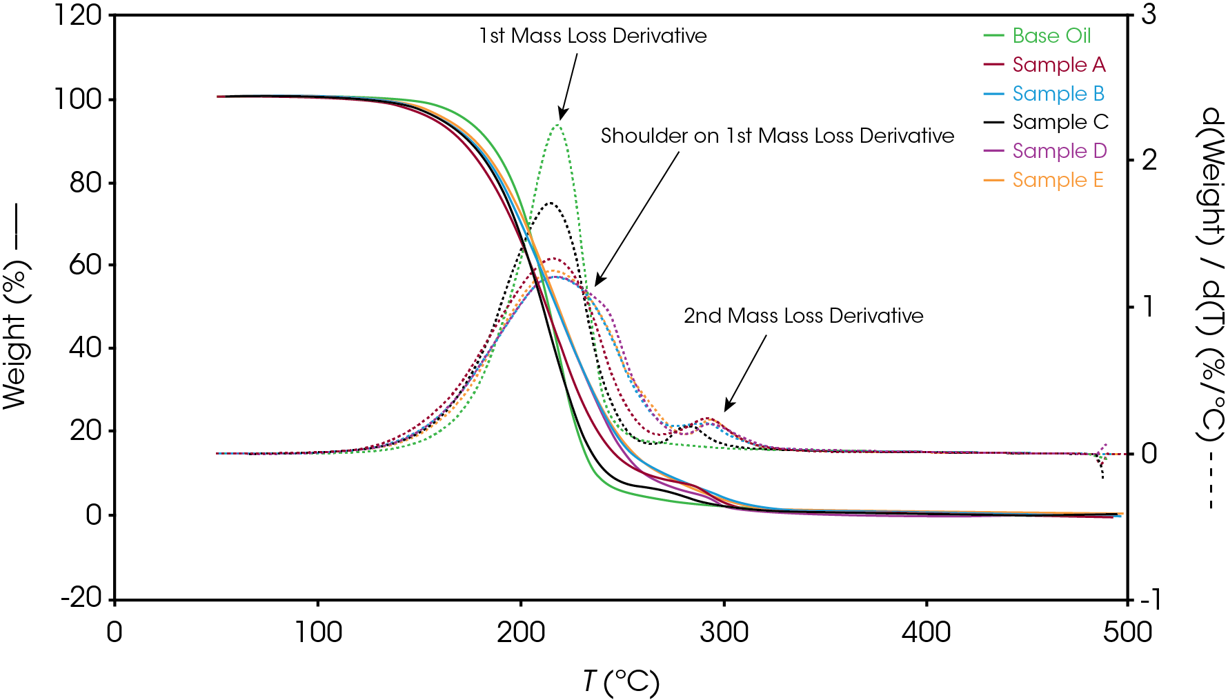
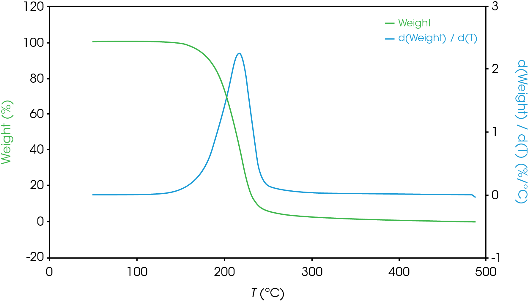
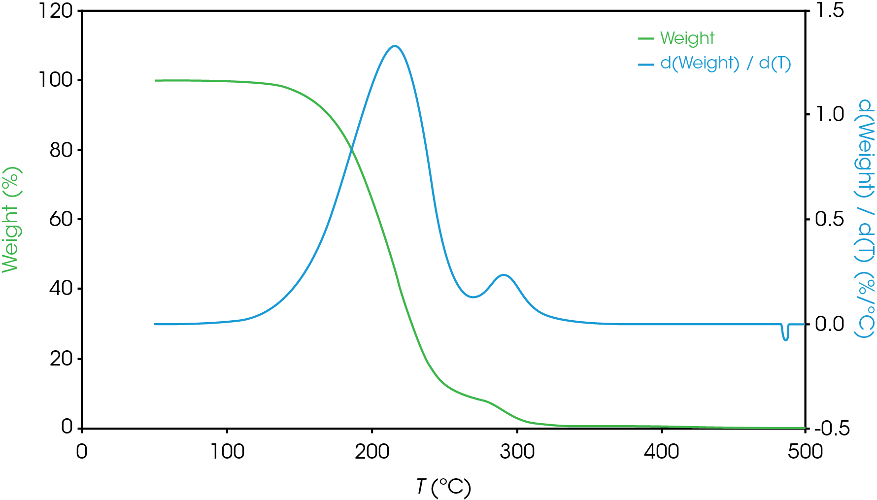
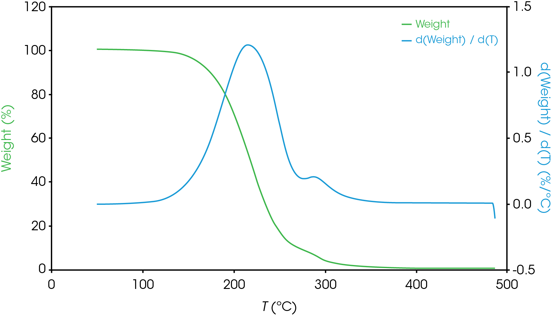
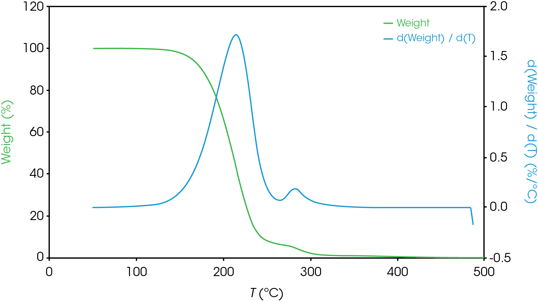
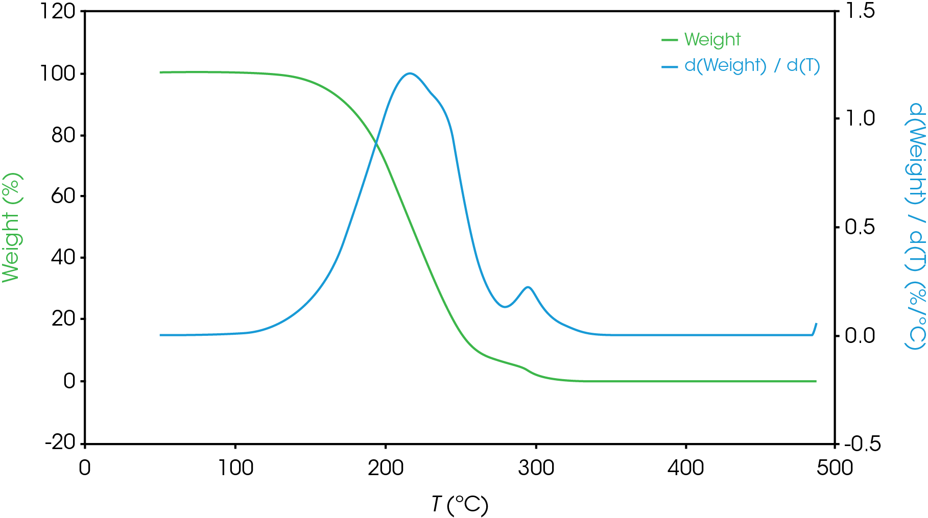
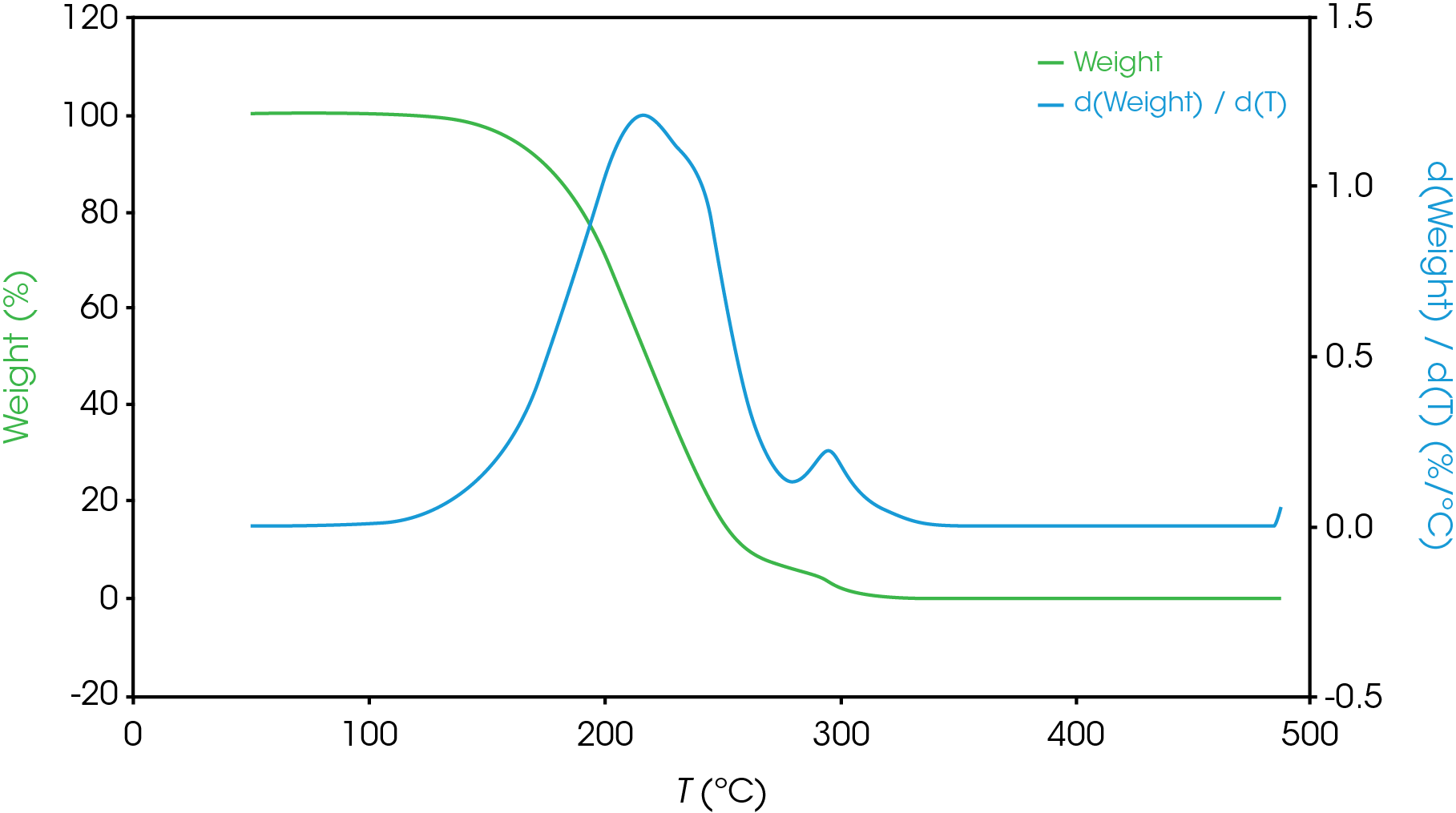
Table 6 summarizes the average of 4 runs of the two main mass losses in each of the samples. Due to the lack of a second mass loss event in the base oil, it is likely that the second mass loss consists mainly of the viscosity modifier.
Table 6. TGA Mass Loss Results (Pt Pans, Average of 4 runs)
| Sample | Mass Loss 1(%) | Mass Loss 2(%) | Residue (%) |
|---|---|---|---|
| Base | 100 | – | – |
| Sample A | 91.4 | 8.34 | 0.36 |
| Sample B | 91.7 | 8.17 | 0.50 |
| Sample C | 93.7 | 6.10 | 0.47 |
| Sample D | 94.0 | 6.25 | 0.00 |
| Sample E | 92.1 | 7.65 | 0.35 |
To gain further understanding of the shoulder observed in some of the samples, the activation energy was plotted as a function of conversion (α). Figure 19 shows a comparison of the activation energy for each of the samples as a function of conversion. Samples A,B,D, and E show an increase in the activation energy as a function of conversion at α ~ 0.4 contrasted with sample C in which the activation energy remains constant until α = 0.8. Samples B, D, and E virtually overlay, sample A shows less deviation compared to samples B, D, and E.
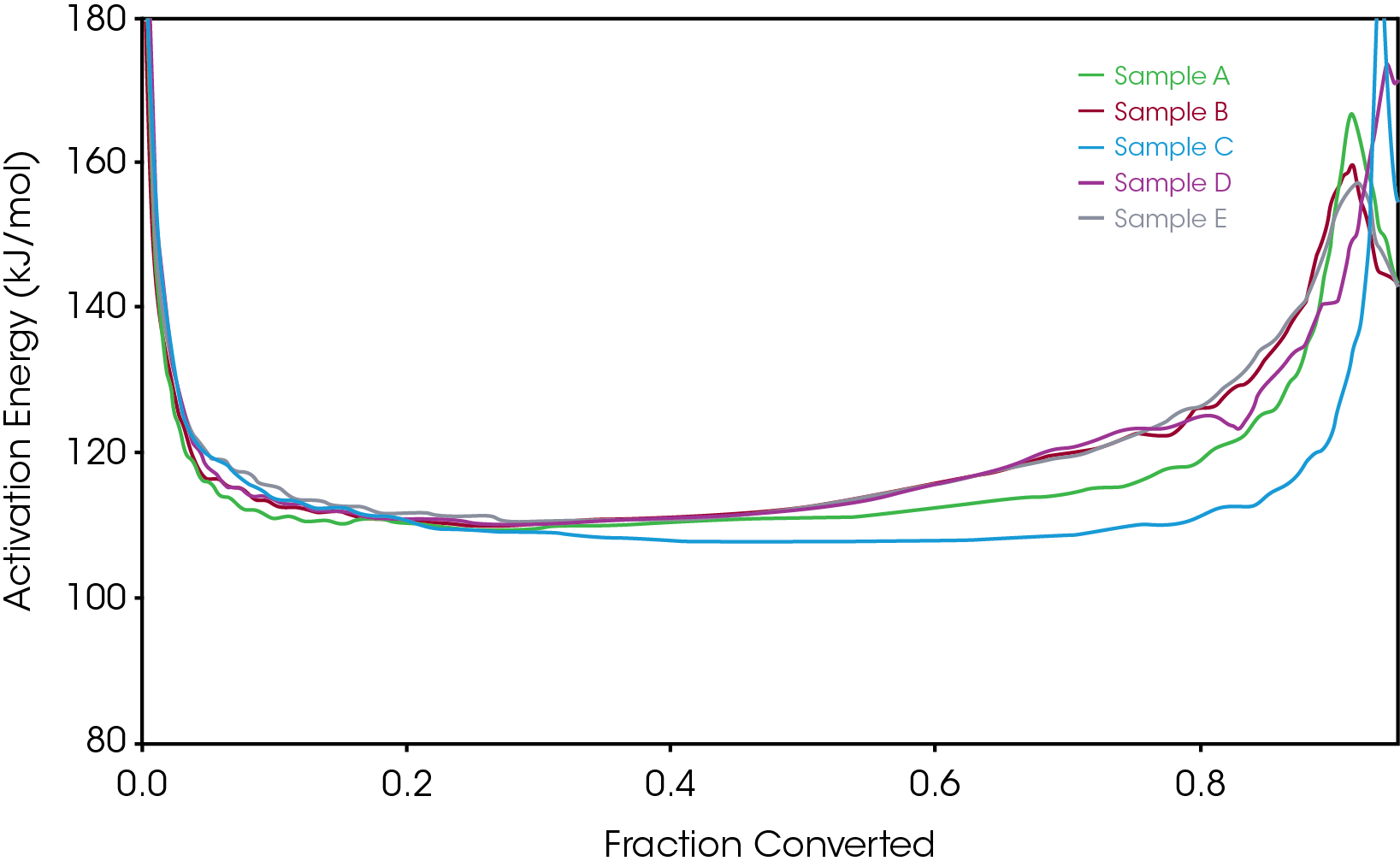
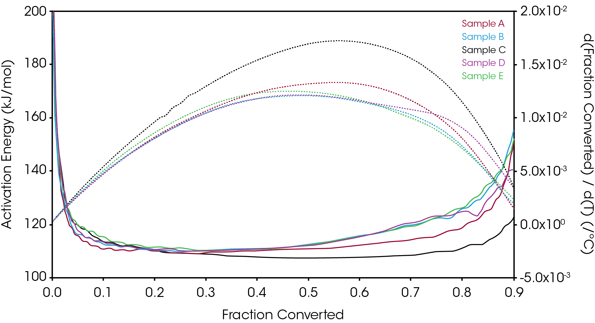
Figure 20 overlays the conversion rate with the activation energy as function of conversion. For each oil sample, the rate maximum occurs at approximately α = 0.6. Samples A and C show similar shaped rate curves. Samples B, D, and E show a marked decrease in rate (dα/dt) compared sample C with sample A intermediate between C and B, D, and E. The TGA experiment measures mass change due to volatilization. The decrease in rate of mass loss occurring at approximately the same extent of conversion is likely due to the formation of a less volatile intermediate. This rate change appears as a shoulder observed in plotting the rate data as function of temperature (dα/dT) described in the previous section.
One possible explanation for the steady increase in activation energy is a summation of processes including the formation of the higher activation energy and less volatile intermediate. It would also be necessary to assess any potential contribution of decomposition of the viscosity modifier as an increase in activation energy is often observed in polymers that undergo autocatalytic decomposition [3]. The extensive properties measured in a TGA experiment are additive and it may not be possible to extract information about the real rate of reaction from any single process [13].
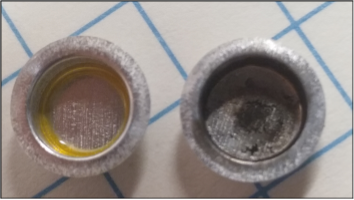
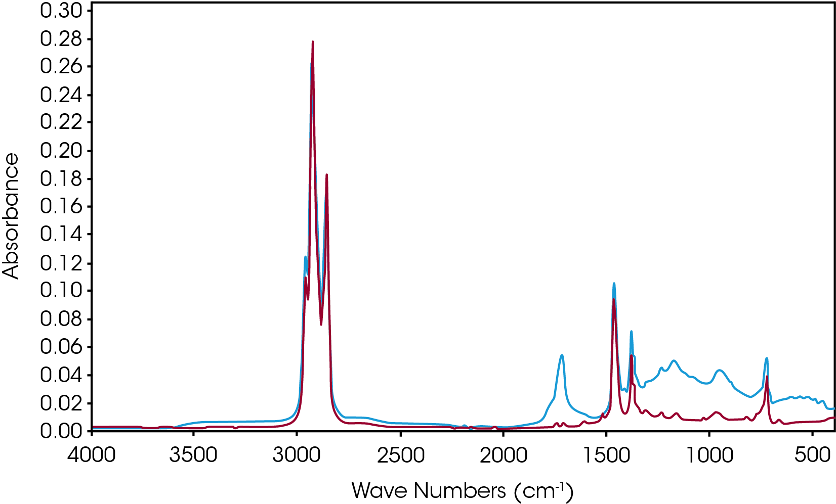
During a preliminary investigation oxidative induction time data (OIT) was obtained using the protocol of ASTM D6186. For sample D, we occasionally obtained what appears to be a polymeric material almost resembling a varnish. This material was very hard and is also difficult to remove from the aluminum pan. This material is shown in left side of the photograph in Figure 21. Generally, char was obtained and shown in the right side of the photograph. An infrared spectrum (Figure 22) shows the polymeric material to be a mainly esters, γ-lactones and other constrained carbonyl species. The constrained carbonyls may be indicative of the length of some of the branches in this sample as we might expect hydroperoxides, esters, and aldehydes. In fact, we have no evidence of aldehydes at all. Sample D also shows the most significant shoulder in the derivative of mass loss with respect to temperature [Figure 17].
Based on this observation, the activation energy and rate data, it seems likely samples A,B,D, and E form a higher molecular weight or polymeric intermediate during the decomposition indicated by the shoulder observed in the derivative of the mass loss curve. This shoulder in the derivative curve is not observed in sample C or in the base oil. Of course, the possibility of breakdown of the viscosity modifier may also be a contributing factor.
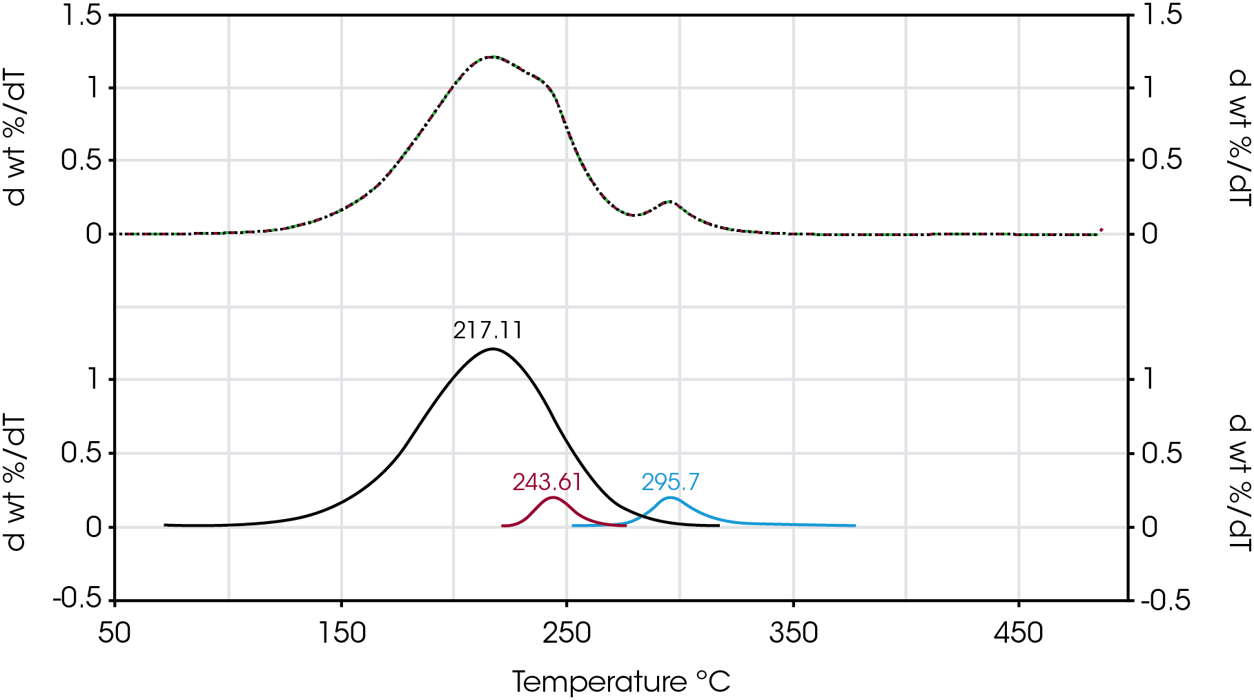
An attempt to improve the data resolution was made by fitting the derivative of the mass loss curve with respect to temperature and to obtain a weighted fraction of the overall mass loss events. Figure 23 shows an example of curve fitting of the derivative of mass loss with respect to temperature for Sample D to obtain the fractional contribution of three mass losses including the shoulder.
Table 7. Summary of Mass Loss Data Fit Using Pearson IV Model (Average of Four Repetitions)
| Sample | Mass Loss 1 | T @ dW/dT Max | Mass Loss 2 | T @ dW/dT Max | Mass Loss 3 | T @ dW/dT Max | Curve Fit | Residue (%) |
|---|---|---|---|---|---|---|---|---|
| % | °C | % | °C | % | °C | r2 | Std Error (%) | |
| Base | 100.0 | 217.4 | 0.00 | – | 0.00 | – | ND | ND |
| A | 87.3 | 214.6 | 1.33 | 229.2 | 11.3 | 291.8 | 1.000 | 0.76% |
| B | 89.3 | 216.0 | 3.49 | 241.1 | 7.13 | 291.7 | 1.000 | 0.71% |
| C | 92.1 | 214.0 | 0.00 | – | 7.86 | 283.2 | 0.999 | 1.07% |
| D | 90.0 | 217.1 | 4.20 | 243.6 | 5.79 | 295.7 | 1.000 | 0.33% |
| E | 91.2 | 215.1 | 3.53 | 243.7 | 5.28 | 294.4 | 1.000 | 0.14% |
The values of mass losses obtained from numerical fit of the rate of mass loss data is summarized in Table 7. The first mass loss based on the derivative curve maximum centered around 217 °C ranges between 87 and 92% and is due to mainly the base oil. The second mass loss centered between 230 and 240 °C is likely due to a larger molecular weight intermediate decomposition product and ranges between 0 and 4%. This second mass loss is not observed in sample C or in the base oil. The third mass loss centered between 283 and 295 °C is 11% for sample A, approximately 7 and 8% for samples B and C respectively and 5 and 6% for samples D and E respectively. Most likely this third mass loss is due mainly to the viscosity modifier and is absent from the base oil.
Conclusions
For this analysis, modulated TGA is used as an additional tool for determining the oxidative stability as well as obtaining additional insight into the degradation mechanism of five commercially available engine oils. In addition to standard TGA data, one can also obtain Arrhenius parameters which can be used to compare relative stability as well as estimate time to failure using ASTM E1641 and E1877 test methods. The advantage is that there is only one mTGA experiment needed and the activation energy is plotted as a calculated signal by the instrument software. Potential distortion of Arrhenius data due to physical or chemical changes as a function of heating rate at levels of conversion are minimized in the modulated TGA experiment. The activation energy can be plotted as a function of temperature for a very broad range of conversion.
Plotting the activation energy as a function of conversion and comparing to rate data indicates that a more stable, less volatile intermediate is formed in 4 of the 5 samples at about 40% mass loss. This intermediate is also apparent when plotting the rate of mass loss data as a function of temperature and appears as a shoulder in the curve. If this less volatile intermediate is a polymeric species, it is not contributing to the lubricity of the oil and likely to deposit on the reservoir screen potentially impeding oil flow to the engine. Numeric analysis of the derivative of mass loss curve is used to estimate the relative contributions of each of the mass losses to the overall mass loss with sample C showing two mass losses, samples A,B,D, and E showing three mass losses indicated by a shoulder on the main mass loss, and the base oil showing a single mass loss. The highest temperature mass loss event in the samples is likely due mainly to the polymeric viscosity modifier.
References
- M. Reading, “Modulated Temperature Scanning Calorimetry – Theoretical and Practical Applications in Polymer Characterization,” in Hot Topics in Thermal Analysis and Calorimetry, vol. 6, J. Simon, Ed., Springer, 2006.
- S. Aubuchon and R. Blaine, “Recent Developments In the Application of Thermal Analysis to Polyolefins,” TA248.
- R. Blaine and B. Hahn, “Obtaining Kinetic Parameters by Modulated Thermogravimetry,” Journal of Thermal Analysis, vol. 54, pp. 695-704, 1998.
- A. Lacey, D. Price and M. Reading, “Theory and Practice of Modulated Temperature Differential Scanning Calorimetry,” in Theory and Practice of Modulated Temperature Differential Scanning Calorimetry; Theoretical and Practical Applications in Polymer Characterisation, Springer, 2006, pp. 1-212.
- ASTM, “ASTM E1641 Standard Test Method for DecompositionKineticsby Thermogravimetry,” 2007.
- “TA125,” [Online]. Available: www.tainstruments.com.
- T. Kujirai and T. Akahira, “Effect of Tempeature on the Deterioration of Fibrous Insulating Materials,” Inst Phys Chem Res, 1925.
- J. Flynn, “The Historical Development of Nonisothermal Kinetics,” Polymer Chemistry Section, Polymers Division, Institute for Materials Research, pp. 1111-1126, 1969.
- J. Flynn and D. B, “Steady-State Parameter Jump Methods and Relaxation Methods in Thermogravimetry,” Thermochimica Acta, vol. 15, pp. 1-6, 1976.
- ASTM, “ASTM E2958 Standard Methods for Kinetic Parameters by Factor Jump/Modulated Thermogravimetry,” 2014. [Online]. Available: www.ASTM.org.
- J. Browne, “TA431 – Deconvolution of Thermal Analysis Data Using Commonly Cited Mathematical Models,” 2020.
- A. E1877, “Standard Practice for Calculating Endurance of Materials from Thermogravimetric Decomposition Data,” ASTM International, 2005.
- Vyazovkin, “Conversion Dependence of Activation Energy for Model DSC Curves of Consecutive Reactions,” Thermochimica Acta, vol. 236, pp. 1-13, 1994.
- Noria Corporation, “The Lowdown on Oil Breakdown,” Machinery Lubrication, 2003.
Acknowledgement
The author would like to thank Mr. Luca Salvi of ExxonMobil who kindly provided a sample of base oil, Dr. Eleanor Riches, Dr. Mike Jones, Dr. Gordon Jones, Dr. Jeff Goshawk, Dr. Caitlyn DaCosta, Mr. Yash Adhia, and Mr. Timothy Browne of Hino for discussions of analysis of lubricant oils in commercial vehicles.
Click here to download the printable version of this application note.

