Keywords: Thermoset, crosslinking, polymer, crosslinking density, DMA, rheology
RH102
Abstract
Thermosetting polymers have been widely used in a variety of industries, such as electronics, automotive, and aerospace. The performance of thermoset materials is strongly influenced by the base polymer architecture, processing conditions, and filler compositions. Examples of commonly used thermosets include epoxies, crosslinked polyurethanes, and polyesters, filled vulcanized rubber elastomers, and some formaldehyde foams.
The degree of crosslinking in a thermoset is a critical parameter that has a major influence on the mechanical strength and visco-elasticity of the material. For an unfilled thermosetting polymer, the percentage of crosslinking (also called the crosslinking density) can be quantitively calculated using both rheological and DMA measurements. In this application note, we elaborate in detail on how to set up a rheological test method to measure the modulus of a thermoset in the rubbery plateau region and then, further, to calculate the crosslinking density.
Introduction to Dynamic Mechanical Analysis
Dynamic oscillatory testing is a very important method for characterizing thermoplastic and thermoset materials. It is usually the best way to determine a material’s viscoelastic properties, which can be related to molecular architecture, processability, curing kinetics for thermosetting materials, and end-use performance [1].
In dynamic testing, one imposes a sinusoidal strain, at a particular frequency and measures the resultant stress, or vice versa. Imposing a sinusoidal strain and measuring the resultant stress in a shear deformation mode is illustrated in Figure 1. Where γ is the shear strain; σ is the shear stress, and ω is the angular frequency.
The ratio, σ0/γ0, is the complex modulus. The phase angle, δ, which is the shift between the input and the output sinusoidal waveform, is an indication of the viscoelastic nature of the material. If δ is 0 rad (0º), the material is purely elastic; if δ is π/2 rad (90º), the material is purely viscous. If 0 < δ < π/2 rad, the material is viscoelastic.
In a dynamic rheological measurement, if the sample is a liquid or soft solid (e.g., paste or gel), it is mostly tested between a parallel plate or a cone and plate. If the sample is in a stiff solid state, then it is tested in the torsional mode. All rheological tests are conducted under a shear deformation mode, so the measured modulus is defined as G.
A DMA is used to measure the viscoelastic properties of sloid samples. The sample can be in a variety of different shapes such as thin film, rectangular bar, etc. The dynamic tests are conducted under a linear deformation mode such as tension, bending, or compression. Therefore, the reported modulus in a DMA test is defined as E.
The relationship between these moduli is based on equation (1), where ν is the Poisson’s ratio of the material. In general, the Poisson’s ratio of polymeric materials ranges from 0.3 to 0.5.
E = 2G (1+ν). (1)
The key parameters that one gets from a rheology and a DMA dynamic testing are shown in Table 1.
Typical dynamic tests that can be performed on a rheometer and a DMA include strain/stress sweeps, time sweeps, frequency sweeps, temperature ramps, and temperature steps/sweeps.
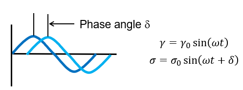
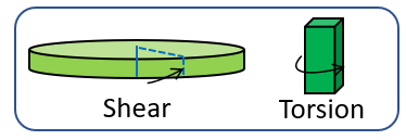
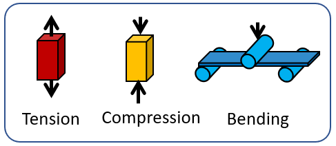
Table 1. Dynamic oscillatory parameters
| Parameter | Symbol | Equation |
|---|---|---|
| Complex Modulus (Pa) | G* E* |
σ0/γ0 τ0/ε0 |
| Storage Modulus (Pa) | G’ E’ |
G*(cos(δ)) E*(cos(δ)) |
| Loss Modulus (Pa) | G” E” |
G*(sin(δ)) E*(sin(δ)) |
| Tan Delta | Tan δ | G”/G’ = sin(δ)/cos(δ) E”/E’ = sin(δ)/cos(δ) |
| Complex Viscosity (Pa-sec) | η* | G*/ω, where ω is the angular frequency (rad/sec) |
Measuring and Calculating the Crosslinking Density of a Thermoset
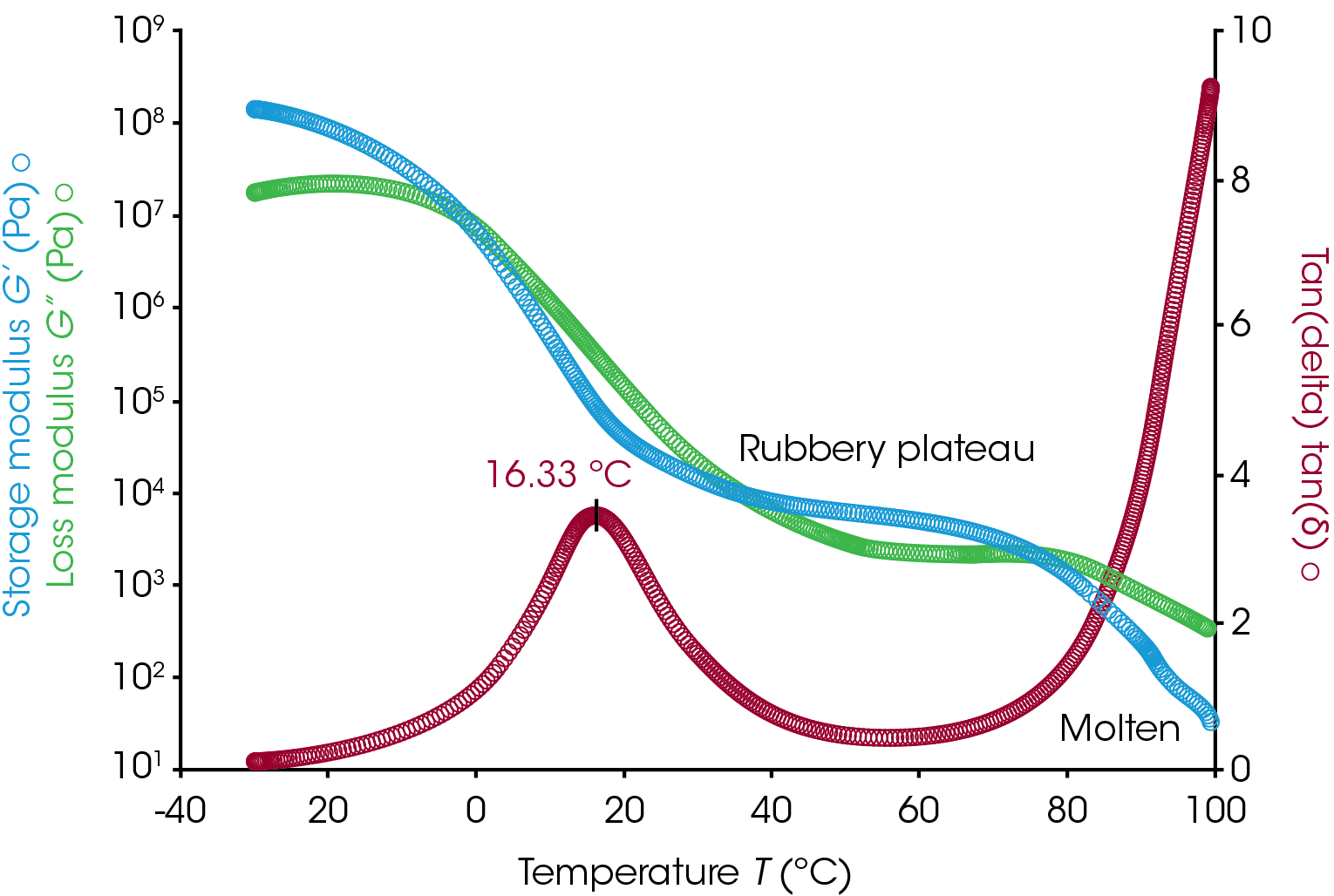
Figure 2 shows a dynamic temperature ramp test result of a linear polymeric adhesive sample. This measurement was conducted using an 8 mm parallel plate geometry under shear deformation on a rheometer. The temperature ramp test was run from -30 °C to 100 °C at a heating rate of 3 °C/min. The test frequency was set at 1 Hz with a small strain that was within the linear viscoelastic region of the sample. As can be seen from the test result, the glass transition temperature (Tg, based on the peak of tan delta) of this linear adhesive polymer is at 16.33 °C. Above Tg, the storage modulus (G’) of the polymer shows a plateau over a temperature window between 40 °C to 70 °C. Then at temperatures greater than 70 °C, this polymer becomes molten with G” being greater than G’, and the sample flows like a viscous liquid. The value of the rubbery plateau modulus (Ge) is correlated with the polymer chain entanglement.
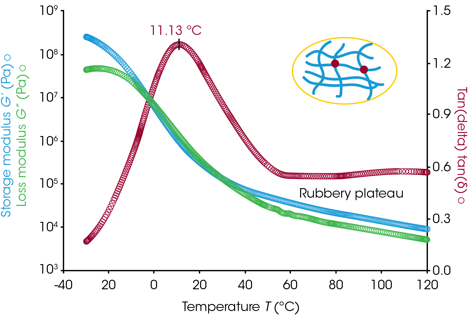
If the polymer is partially crosslinked, then its molten state will not be observed in a temperature ramp test. After Tg, the rubbery plateau area will extend up to higher temperatures until the polymer starts to decompose. Figure 3 shows an example temperature ramp test result of a partially crosslinked adhesive sample. The storage modulus remains greater than loss modulus at temperatures above the normal molten temperature of the polymer without crosslinking. For a crosslinked polymer, the storage modulus value in the rubbery plateau region is correlated with the number of crosslinks in the polymer chain.
There are a number of references in the literature reporting using the modulus measured within the rubbery plateau region to quantitatively calculate the polymer crosslinking density [2,3]. First, the molecular weight between crosslinks can be calculated from the G’ measured within the plateau region using equation (2)
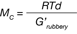
Where Mc is the molecular weight between crosslinks, R is the universal gas constant, T is the absolute temperature and d is the density of the polymer.
Then, the crosslinking density of the polymer can be calculated using equation (3)
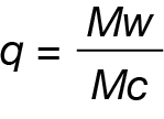
Where Mw is the molecular weight of the monomer, and q is the crosslinking density.
Alternatively, researchers have reported using the DMA test results for the calculation of the crosslinking density [4]. Equation 4 is based on the assumption that E is 3 times greater than G, when Poisson’s ratio is 0.5.
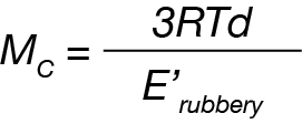
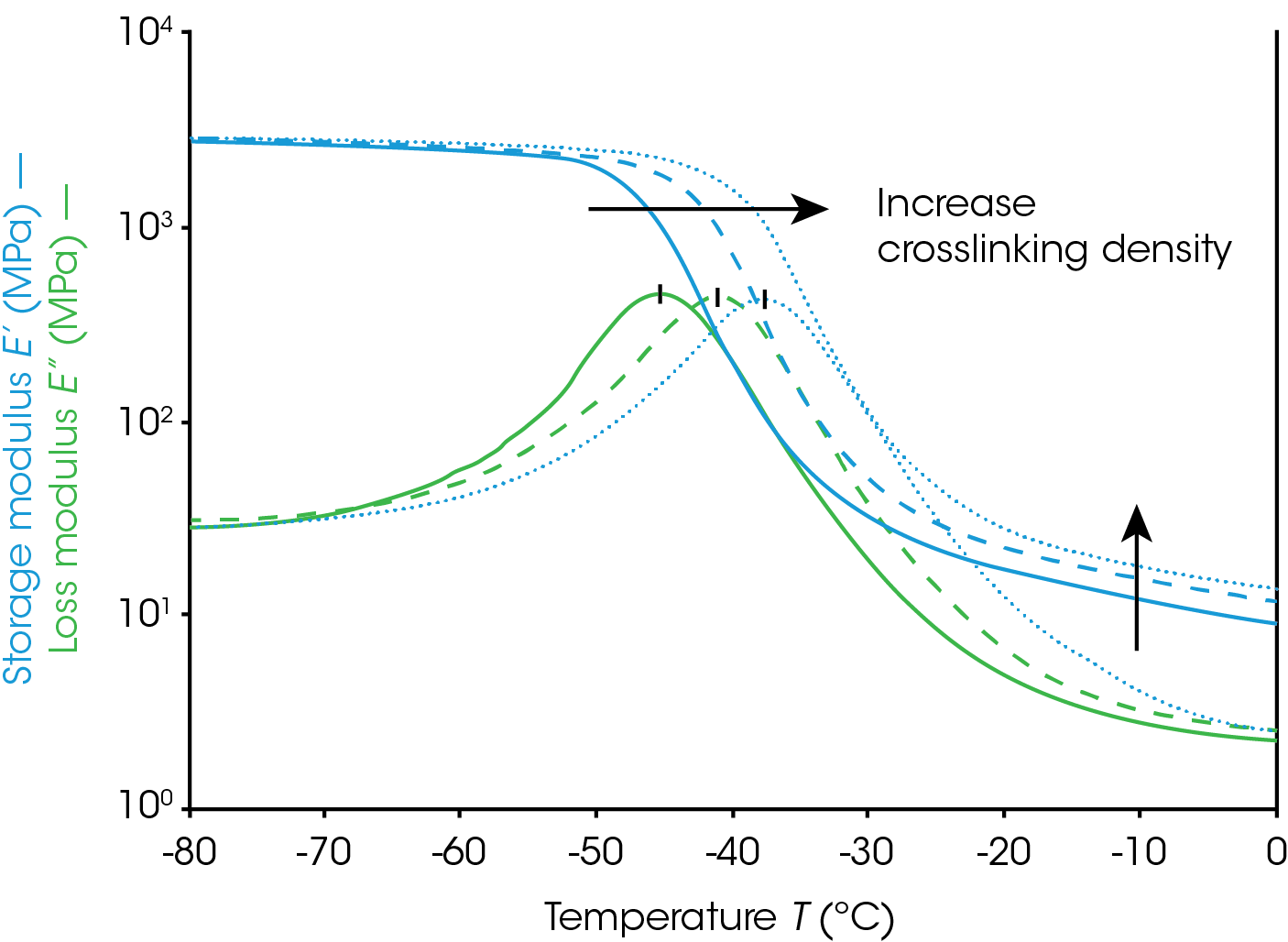
Figure 4 shows the results of testing a series of rubber elastomers with different amounts of crosslinking using a DMA in the tension mode. As can be seen from the graph, the measured rubbery plateau modulus increased with increasing the degree of crosslinking. In the meantime, the glass transition is also observed to shift to higher temperatures.
To simplify the test method and shorten the measurement time, one can also program a short dynamic time sweep test at a temperature that is within the rubbery plateau region, take the measured storage modulus, then use equation (2) or (4) to calculate Mc. Please note that using the rubbery plateau modulus to calculate the crosslinking density is only applicable to unfilled thermoset polymers.
References
- C. W. Macosko, Rheology: Principles, Measurements, and Applications; Wiley-VCH, New York, New York (1994)
- F. Abd-El Salam, M. H. Abd-El Salam, M. T. Mostafa, M. R. Nagy, M. I. Mohamed, Journal of Applied Polymer Science, 90, 1539–1544 (2003)
- K.S. Santhosh Kumar et al. European Polymer Journal, 43 2504–2514, (2007)
- I. M. Barszczewska-Rybarek, A. Korytkowska-Walach, M. Kurcok, G. Chladek, J. Kasperski, Acta of Bioengineering and Biomechanics. Vol. 19, No 1, (2017)
- L E Nielsen “Mechanical Properties of Polymers and Composites”, page 169, 2nd edition, Marcel Dekker, 1994


